
Summary of Contents for PMC M20d Series
- Page 1 M20d Series Temperature & SVG Controller USER’S MANUAL For avoid wrong operation to make human injured or machine damage, please read this instruction carefully before use the instrument. Ver. 3.3a...
-
Page 3: Warranty
WARRANTY We warrant that this product will be free from defects in materials and workmanship for a period of two (2) years from the date of shipment. If any such product proves defective during this warranty period, we, at our option, either will repair the defective product without charge for parts and labor, or will provide a replacement in exchange for the defective product. -
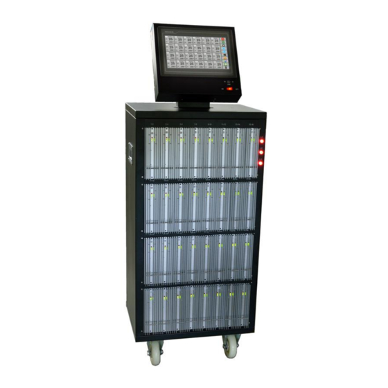
Page 4: Chapter 1 Introduction
Chapter 1 Introduction 1.1 M20 Series Mainframe Configurations The M20 controller is made up of 4 different models of mainframes which change based on the number of zones required. These are referred to as M20-XS, M20-S, M20-M, and M20-L. All of the mainframes employ the same temperature control module M20-M2, and the same sequence valve gate control module M20-V2. -
Page 5: Specifications
1.3 Specifications M20-XS M20-S M20-M M20-L Model User Interface Full color LCD touch screen Display Size 7.0" 7.0" / 10.2" 10.2" Max. Total Zones Max. Temp. Zones Max. Sequence Zones 3-Ph+E(4 wire) 200-240Vac Power Supply 3-Ph+N+E(5 wire) 380-415Vac Working Conditions 0~55℃... - Page 6 1.4 Features Cabinet Temperature only, SVG only, or Combination Full color LCD touch screen Max. 120 zones English/Spanish/Chinese CE compliant Fixed on mainframe or Stand-alone Control Modules Alarms & Protection “All in one” control module Sensor broken /reversed /shorted /mis-connected 2-zone per temperature module (15 Amp per zone) Load broken /shorted /over-rated 6-gate per SVG module...
-
Page 7: Pins Description
1.6 Typical Sequence Trigger & Output Connectors Wiring SVG Input Wiring SVG Output Wiring Signal Pins Description Type Trigger Sees a closed condition or DC24V as a signal to start Normally Open Dry Contact 1 & 2 Input the timer on the valve sequence Or DC24V Accepts a voltage source input that relates to the main Screw... - Page 8 1.8 System Wiring (only temperature control) (power wiring depends on the voltage specification) - 6 -...
-
Page 9: Power Wiring
1.9 Power Wiring 3-Ph+N+E (5 wire) 380-415Vac 3-Ph+E (4 wire) 200-240Vac - 7 -... -
Page 10: Chapter 2 Inspection & Installation
Chapter 2 Inspection & Installation 2.1 Unpacking and Inspection 1. After unpacking, inspect the mainframe and check for any damage that may have occurred during shipment. 2. Check the circuit breaker disconnect and neon phase voltage indicators for damage. 3. Check for proper operation of circuit breaker by flipping breaker on and off with no voltage applied. 4. - Page 11 2.3 Connecting the Power Cable (except M20-XS, M20-S Series) 1. Select the power input wire size according to the load power, and the national and local electrical codes. (if required) 2. Remove the metal cover of the power input terminal block by removing screws around its perimeter. 3.
-
Page 12: Chapter 3 Connecting The System To The Mold
Chapter 3 Connecting the System to the Mold 3.1 Prior to Start Up ● Check that the system is completely disconnected from the power source. ● Clean up any water, oil, dirt, cleaning fluids etc. that may have spilled during a mold change or since the last production run. -
Page 13: Chapter 4 Operator Interface
Chapter 4 Operator Interface 4.1 Main Interface The main interface is used to monitor, log in the system and general operations. 4.1.1 Temperature Control Icon Button Mode, 24-zone per page, Resolution 0.1 is not checked Icon Button Mode, 42-zone per page, Resolution 0.1 is checked - 11 -... - Page 14 ● Function Button: Icon mode is the default setting, Text mode can be selected on system setting page. ● 24 or 42 zones per page: 24-zone is the default setting, can be alternated on system setting page. ● Resolution: 1 is the default setting, 0.1 can be selected on system setting page. ⑴...
- Page 15 4.1.2 Sequence Valve Gate Control (Icon Button Mode) [Run] (green)/[Stop] (red): Run or Stop temperature & valve gate control of all zones. In Stop mode, shows Run; and in Run mode, shows Stop. [Auto]: Place the sequence valve gate control of all zones in Auto mode. [Manual]: Place the sequence valve gate control of all zones in Manual mode.
- Page 16 4.2 USB Port The USB port on the M20 series is intended to be used to copy pattern (mold) setup files to and from the system. The screen for importing or exporting mold setups is displayed in the Group Setup Screen. These mold setup files can be copied to other M20 controllers that support the same file type.
-
Page 17: Chapter 5 Security & System Setting
Chapter 5 Security & System Setting 5.1 Login / Logout the System In order to avoid accidents happened, and protect the system data, different level operators have different authorities. To achieve the corresponding authority, the operator should login the system by his or her user name and password before operation. -
Page 18: System Setting
5.2 System Setting Touch [System] on the main interface of temperature control, then you can enter the System Setting Screen. 5.2.1 Security ● Authorization: You can manage the users, include add, copy and delete user. You can also check the user’s properties. The user’s name allows to be edited. - Page 19 ● Authorized to Change Setpoint / Everyone Can Change Setpoint: Touch it to change the authority setting for operators not login. Display Authorized to Change Setpoint: It means current setting is Everyone Can Change Setpoint. Operators not login the system can run/stop the system, and change the setpoint. Display Everyone Can Change Setpoint: It means current setting is Authorized to Change Setpoint.
-
Page 20: Auxiliary Functions
5.2.5 Other blue - unchecked, green - checked) ● Keep the data: Zones’ work state (Auto or Manual, and power output % in manual mode) will be the same as before power off when re-start and run the system. ● Button text: Function Buttons will be showed by TEXT mode instead of ICON mode. ●... - Page 21 1) Click the [Sensor Fault Solution] to enter its setting interface. 2) Set the Major ID and its Related ID. You can preset 12 pairs. 3) Touch the [Enable] or [Disable] to activate or stop this function. blue - unchecked, green - checked) 4) Click [Quit] closing this interface.
- Page 22 2) Appoint zones for each group. If you need to divide all zones into 2 groups, you can only appoint zones for group 1, then the rest zones will be the second group. 3) Set the target tolerance for each group. e.g.
-
Page 23: Chapter 6 Temperature Control Operations
Chapter 6 Temperature Control Operations 6.1 Control Modes [Auto] This type of control is a “closed-loop” system and requires a thermocouple feedback signal. The controller uses a PID algorithm to determine the required output power to hold the actual temperature value equal to the setpoint. - Page 24 6.3 Detail Parameters for Each Zone Parameter Description Setpoint Target temperature: full scale. High deviation alarm value. Alarm High When actual value > Setpoint+Alarm High, zone alarms and shut off output. Low deviation alarm value. Alarm Low When actual value < Setpoint+Alarm Low, zone alarms. Sensor Type J –...
- Page 25 Parameter Description To reduce the influence of interference. Filter The larger the value is, the slower the controller responses. When it is too large, the controller may be out of control. Load-short Diagnostic sensitivity for load shorted, 0~100. The greater the value is, the lower the sensitivity. Recommended setting is 0. Sensitivity Heating speed slowing function.
-
Page 26: Group Setting
6.4.1 Group Setting You can change parameters for all zones by Global Config, or change parameters for zones with same background color by Group Config. 6.4.1.1 Global Config Used to set parameters for all zones. 1) Click the parameter’s value needed to be set, and then the small keyboard will appear. 2) Input the required value. - Page 27 6.4.2 Mold Patterns You can manage the mold patterns by Pattern Management. M20 can save maximum 24 sets mold parameters. You can import, export, and delete the pattern files, etc. NOTE : The mold pattern file is a database file containing the control parameters of each zone. 6.4.2.1 New Pattern’s Config Export 1.
- Page 28 6.4.2.3 Pattern Files Management Click the [Pattern Files Management] to enter the management screen. You can browse the pattern files in USB disk or local, and manage these files. ⑴ Files location selected: [Local File] or [USB File]. ⑵ [Delete]: used to delete the selected file; [Import]: used to import the files selected from the USB disk to the local;...
-
Page 29: Zone Setting
6.5 Zone Setting Touch the Actual Temperature on the main interface, then you can enter Zone Parameters Setting Screen (different authority can see different parameters). 6.5.1 Non-Login Status (if everyone can change setpoint) ● Change Setpoint: by [<] [∧] [∨]. ●... -
Page 30: Graph Display
● Run or Stop this zone: touch [Run] / [Stop]. ● Turn off or turn on this zone: touch [OFF] / [ON] ● Change Control mode of this zone (in running state): touch [Auto] or [Manual]. ● Activate Boost function (fast heating speed): touch [Boost], and the power output percent will be added 20% (max.100%) for 15s. - Page 31 6.6.1.1 Select Zone ID to View On Present Curve Screen, you can view max. 6 zones. 1) Click the ID number to enter curve’s ID selection mode. 2) Input the ID number which you want to view the curve, and then click [YES] to confirm. 6.6.1.2 Select the Curve Display The box before the ID number is used to select the curve display.
- Page 32 Each History Curve Screen can display 10 zones. You can select the ID group to view, or back to present curve by [Quit] . 6.6.2.2 Select the Curve Display The box before the ID number is used to select the curve display. blue - unchecked, green - checked You can click it.
- Page 33 6.6.2.3 Select the Curve Start Time When you enter the History Curve Screen, the curve start time is 2 hours ago. You can click the Start Time to input a new one (the time format should be same as the original one). And you can select the start time by Select a specified time.
-
Page 34: Alarm Record
6.7 Alarms Touch [Alarm] on the main interface, then you can enter the Alarm History Screen. 6.7.1 Alarm Record 6.7.1.1 Select the Record Period You can click the Start Time to input a new one (the time format should be same as the original one). And then the End Time. -
Page 35: Alarm Status
6.7.3 Alarm Status Alarm on Alarm on Alarm History Remark Zone Thermocouple is broken or Controller will shut off the output. T/C Broken damaged. Check the sensor or switch to manual mode. Controller will shut off the output. Thermocouple is reversed. Reversed Check the sensor or switch to manual mode. -
Page 36: Chapter 7 Svg Control Operations
Chapter 7 SVG Control Operations Touch [SVG] on Temperature Control main interface, then you can enter Sequence Valve Gate Control main interface. And touch [Temp] on Sequence Valve Gate Control main interface, then you can enter Temperature Control main interface. Notes: 1) Zone’s output type is selected on modules with jumpers. - Page 37 7.2 Start Trigger Modes This SVG controller supports gates open/close 1~2 times in a complete cycle. If the start trigger duration time is longer than a complete cycle of gate open/close, then the control process is: 1) When the controller receives the start trigger, it initiates the run timer from the zero time position. 2) Gates open after T1 time (or screw position is T1) from the controller receives start trigger;...
- Page 38 Mode 1: The gate open/close cycle will be terminated and gate close when the start trigger ends. The controller initializes the run timer when it receives the new start trigger. 1) When the controller receives the start trigger, it initiates the run timer from the zero time position. 2) Gates open after T1 time (or screw position is T1) from the controller receives start trigger;...
- Page 39 Mode 3: The gate open/close cycle will be terminated and gate close when the new start trigger comes. The controller initializes the run timer when it receives the next new start trigger. 1) When the controller receives the start trigger, it initiates the run timer from the zero time position. 2) Gates open after T1 time (or screw position is T1) from the controller receives start trigger;...
-
Page 40: Gate Setup
7.5 Gate Setup Touch the Gate Status “Open” or “Close” on the main interface, then you can enter Gate Setup Screen (different authority can see different parameters, and no parameter can be seen without login). 7.5.1 Operators-Login Status ● Set T1 ~T4: click the value to call up small keyboard. - Page 41 ● Select background color of this gate: touch [Color] to call up background color setting. Select a color you want to use as background of this gate, and then click [YES] to set the figures and leave the screen. ● Turn off or turn on this zone: touch [OFF] / [ON] ●...
-
Page 42: Chapter 8 Run/Stop System
Chapter 8 Run/Stop System 8.1 Run System Touch [Run] on the main interface of temperature control or SVG control to run the system. Temperature Control All zones start to work in Auto mode (disable keep the data in system setting) or the mode before power off (enable keep the data in system setting) except the module is turned off by zone setting.
Need help?
Do you have a question about the M20d Series and is the answer not in the manual?
Questions and answers