Table of Contents
Advertisement
Quick Links
Advertisement
Table of Contents

Related Manuals for Simplex STS


Summary of Contents for Simplex STS
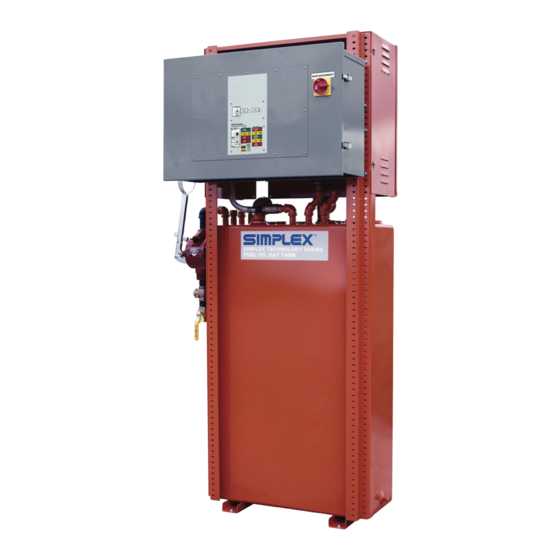
- Page 1 STS DAY TANK PACKAGED DAY TANK SYSTEMS...
- Page 2 Last revision date: March 2, 2021 For the most up-to-date information for this product and others, please contact Simplex, Inc. at (800) 637-8603 or visit us on the web at http://www.simplexdirect.com.
-
Page 3: Table Of Contents
Table of Contents 1 WARNINGS AND CAUTIONS ........2 Safety Information Symbols ............2 Cautions ....................2 2 NAMEPLATES AND PLACARDS ........4 3 INSTALLATION .............6 Overview of Use ................6 Installation Operation ..............7 Vent Openings ................10 Day Tank Pump Priming Procedure .........11 4 DAY TANK OPERATION..........12 Automatic Operation ..............13 High Level Fill Disabled ...............13... -
Page 4: Warnings And Cautions
1 WARNINGS AND CAUTIONS The following images indicate important safety afety information: nformatIon ymbolS This General warning symbol points out important information that, if not followed, could endanger personal safety and/or property. This Explosion warning symbol points out potential explosion hazards. This Fire warning symbol points out poten- tial fire hazards. - Page 5 repairing this equipment, place insulative mats over a dry wooden platform. Work on the equip- ment only while standing on such insulative mats. • The National Electrical Code (NEC), Article 250 requires the frame of the equipment to be connected to an approved earth ground and/or grounding rods.
-
Page 6: Nameplates And Placards
2 NAMEPLATES AND PLACARDS... -
Page 8: Installation
Never locate a Day Tank system above a residential living space. If you have any questions regarding Day Tank installation, call Simplex service at (800) 637-8603 (24 hrs.). See dimensional drawing for port sizes. All plumbing to and from the Day Tank should be black iron pipe or copper tubing. -
Page 9: Installation Operation
2. Attach the Overflow Pipe. This is an NPT internal connection. Simplex recommends the configura- tion shown in the illustration above. The overflow pipe runs from the Day Tank back to the main storage tank and allows for draining of the tank should it become overfilled. - Page 10 connected or is obstructed the tank will distort and possibly rupture. In installations where the Risk of electric shock! main fuel tank is above ground the overflow pipe More than one Discon- should be connected to an Overflow Tank (Option nect Switch may be re- quired to de-energize #390 Recommended).
- Page 11 7. The pump has been pre-lubricated with heavy oil prior to shipment. Prime the system by using the hand pump (Option 010 or 015) to transfer fuel from the main tank to the Day Tank. If the Day Tank is not equipped with a hand pump, remove the tank inlet priming tee plug and fill the entire inlet line with fuel.
-
Page 12: Vent Openings
Each tank and each compartment of a compartment penIngS tank shall have provision for both normal and emer- gency venting. A vent opening shall be in addition to the filling and withdrawal openings. A vent opening that provides both emergency and normal venting shall have a capacity not less than that specified in the Venting Capacity Table below. -
Page 13: Day Tank Pump Priming Procedure
The Day Tank pump is shipped from the factory pre-primed with SAE 30 oil. On initial start-up the rImIng pump must be manually pre-primed. Do not prime roCeDure the system by running the pump motor! Normally it is not necessary to fill the supply line with fuel to prime the pump. -
Page 14: Day Tank Operation
4 DAY TANK OPERATION The control nameplate consists of a durable, fuel oil resistant, Lexan membrane which contains the Day Tank control pushbutton, switch and status indicators. The control panel contains a Fill Test pushbutton (hold to test L.E.D. lamps), a three position Day Tank Auto-Off-Manual switch, and the following L.E.D. -
Page 15: Automatic Operation
by the prime mover. Dry contacts for Low Fuel Level, High Fuel Level, Leak Alarm, and Not In Auto relays are wired to terminals 1-12 of terminal block TB‘A’ for customer use. The customer may utilize these contacts to annunciate low fuel level and high fuel level. -
Page 16: Fill Test Pushbutton
fuel level. If a High Level Alarm condition occurs and the Day Tank fuel level is reduced to normal levels the High Level L.E.D. will remain illuminated until it is reset by the operator. The operator must place the Day Tank mode selector switch in the Off position and then return it to the Manual or Auto- matic position to reset the High Level failure. -
Page 17: Manual Operation
pump/motor does not energize a low fuel level alarm will be initiated when Day Tank fuel capacity reaches the 25% level. The low fuel alarm relay LFR energizes, the Low Level Alarm L.E.D. is illuminated, and LFR dry contacts close. The Day Tank user may utilize these contacts to sound an alarm horn or provide an input to a remote annunciator. - Page 18 excess of pump capacity. The lag pump and its separate level controller, acting as a backup senses a drop in fuel level below 50% and starts the lag pump, which then continues to run, along with the lead pump, until the tank is full. Multi-function duplex pump controller system providing selectable operat- ing modes, including: •...
-
Page 19: Overflow - Return Tank, Option 383
When the Mode Selector switch is in the Manual position all floatswitches, except the high fuel level floatswitch are over-ridden, and either position Day Tank operation is automatic and the day (Alternate or Both) may be selected. The pumps will tank motor may start at continue to run until Switch #1 is returned to the Off any time! After a motor... -
Page 20: Overflow - Return Pump And Controller Added To The Day Tank, Option 390
Normally the Day Tank operates automatically to verflow control the fuel level between the 50% and normal eturn ump anD full level, which is set at the position of the overflow ontroller DDeD or vent fitting on the tank. An overfill can occur if to tHe the control switch is left in the Manual position, if ptIon... -
Page 21: Maintenance
5 MAINTENANCE The Simplex Day Tank has been designed to require minimum maintenance. All components have been chosen for a long, reliable life. The Day Tank is constantly lubricated by the diesel fuel it transfers. Inspect this tank at least once every year for dam-age, leakage, or rust on both inside and outside the tank. -
Page 22: Troubleshooting
6 TROUBLESHOOTING 1. Pump not primed. 2. Lift is too high. elIvereD 3. Rotation direction incorrect. 4. Check valve installed backwards. 1. Air leak at inlet. nSuffICIent 2. Defective solenoid valve or check valve. elIvereD 3. Lift too high. 4. Pump worn. 5. -
Page 23: Noisy Operation
1. Insufficient fuel supply. oISy 2. Air leaks in the inlet pipe. peratIon 3. Air or gas at the inlet connection. 4. Pump and motor out of alignment. 5. Worn out spider coupling. 6. Pump coupler out of balance. 1. Inoperative foot valve. eQuIreS 2. -
Page 24: Drawings And Parts List
Fuel Supply System. When ordering replacement parts always consult the Parts Legend. When contacting the Simplex Service Department always have your sales order number and drawing number ready for refer- ence. The Job Number and the Drawing Numbers are located on each drawing legend. -
Page 25: Technical Data
Conversion Factors eCHnICal 1HP = 33,000 ft. lbs. per minute PRESSURE AND 1HP = 42.4 btu per minute CONVERSION TABLE 1HP = 0.746 kwhr (kilowatt hours) Feet 1 U.S. gallon = 231 cubic inches Water Water Pipe Volume varies as the square of the diameter; volume in gallons = 0.0034 D L where: D = inside diameter of pipe in inches;... - Page 26 FLAMMABLE Pipe Friction- Fuel Oil 2 LIQUIDS Pressure Drop in PSI per 100 feet of Pipe and Tube FLASH POINTS NOMINAL SIZES - INSIDE DIAMETERS Excerpts from NFPA 325, “Fire Pipe Hazards properties of Flammable Size, 10.0 17.0 23.0 40.0 50.0 Liquids...”...
-
Page 27: Appendix A - Product Warranty
Simplex, Inc., warrants the industrial electrical control, test and accessory equipment and parts and accessories thereof to be the kind and quality described in Simplex’s spec- ifications and to be free from defects in material or workmanship under normal service. - Page 28 Contact Simplex for all your Load Bank and Fuel Supply needs. Simplex, Inc. 5300 Rising Moon Road Springfield, IL 62711 800-637-8603 www.simplexdirect.com This manual and all of its contents Copyright © 20 Simplex, Inc. All Rights Reserved.
Need help?
Do you have a question about the STS and is the answer not in the manual?
Questions and answers