Table of Contents
Advertisement
Quick Links
Advertisement
Table of Contents

Summary of Contents for NexTraq VT-2300
- Page 1 NexTraq VT-2300 Installation Guide Version 1.1...
- Page 2 NexTraq. Under copyright laws, no part of this installation guide may be reproduced or transmitted in any form or by any means, electronic or mechanical, including photocopying and recording, for any purpose, without the express written permission of NexTraq.
-
Page 3: Table Of Contents
Introduction ..........................4 VT-2300 Hardware ........................4 VT-2300 Wiring Diagrams ......................5 Power Cable Diagram ....................... 6 VT-2300 Adapter Cable Diagram ....................7 Equipment and Tools ........................9 Antennas ..........................10 Antenna Installation Types ......................11 Glass Mount ......................... 11 Dashboard Mount ........................ -
Page 4: Introduction
Introduction Following the purchase of VT-2300, there will be several factors to consider prior to its installation, including placement of the VT-2300 hardware and the selection and placement of the antenna(s). This installation guide is designed to provide instructions for the installation of the VT-2300 hardware for use with the NexTraq™... -
Page 5: Vt-2300 Wiring Diagrams
External mounting tabs are provided that allow the VT-2300 to be secured to the chassis of the vehicle. If you are replacing a Wahoo 2 or VT-2200, the VT-2300 will fit in the area you have the previous unit secured. Additional equipment is required to properly mount the VT-2300 hardware and is provided in the installation kit for each VT-2300. -
Page 6: Power Cable Diagram
Power Cable Diagram Fig. 3 Power Cable Description The 4 pin power cable is the only harness needed if install requires ONE positive input sensor / GPIO1 (in addition to normal 3-wire install). PIN2 (green wire) will be covered by heat shrink. Installer will need to cut back heat shrink to expose for sensor install. -
Page 7: Vt-2300 Adapter Cable Diagram
VT-2300 Adapter Cable Diagram Fig. 5 VT-2300 Adapter Cable Position Each wire on the VT-2300 Adapter Cable will be part of a connector. Wires can be cut from a connector when necessary for sensor installs. PIN2 is Negative Input Sensor1/GPIO2. PIN3 is Negative Input Sensor 2/GPIO3. PIN4 is Sink Output/GPIO4 and is used for Starter Interrupt. - Page 8 Fig. 6 VT-2300 Adapter Cable Connectors is composed of three connectors: VT-2300 Adapter Cable Two PIN connector Used with Driver ID Key Fob Reader or Temperature Sensing Probe (Black/Green) Four PIN connector Used with Driver ID Key Fob Buzzer, LED, or any other...
-
Page 9: Equipment And Tools
Equipment and Tools The following is a general list of tools and supplies required for a VT-2300 installation: Recommended Equipment Recommended Supplies Digital Volt and Ohm Meter (DVOM) Electrical Tape Screwdrivers (standard, Phillips, Torx, Hex) Double-sided Tape Wire Strippers/Wire Cutters... -
Page 10: Antennas
Great care should be taken before installing the antennas. The standard antenna type used for the VT-2300 is a combination antenna in the style of either a blade or a puck. Two FAKRA connectors provide connection for GPS (blue) and GSM (violet). -
Page 11: Antenna Installation Types
Antenna Installation Types Glass Mount When mounting the antenna, it should be oriented with the top section facing the sky. NOTE: The blade antenna specifies which side is the bottom. The puck antenna comes with a sticker indicating which side should face the sky. The glass mount provides the best reception for cellular and GPS. -
Page 12: Covert Installation
Antenna placement is optimal underneath a removable plastic cover near the windshield on the top of the dashboard. If no removable cover is present, then removing the front dash bezel, the radio or instrument cluster to gain access under the dashboard is a good alternative position. Placement behind the plastic A pillar cover works well, but should be a second choice. -
Page 13: Vehicle Wiring
Power Find constant 12 volt wire and slide crimp over wire. Slide red fused wire from NexTraq power cable all the way into the holder and crimp with pliers. Cable tie the fused wire to the lead wire. Next, find an ignition wire that is 12 volt when ignition is in the “ON”... -
Page 14: Ignition
Ignition An ignition source is also required for proper installation of VT-2300. Connect the white wire to the vehicle ignition source. This wire can be found in close proximity to the main power wire. Be sure that the tapped wire is a vehicle ignition wire and not an accessory wire. -
Page 15: Vt-2300 Location
Availability of a constant 12-volt power supply In most vehicles, the VT-2300 can be placed inside or underneath the dashboard. The vehicle’s radio can be removed and the unit placed behind the radio. A kick plate can be removed and the unit can be safely secured to a firewall or zip-tied onto a permanent fixture. -
Page 16: Mounting Location
Fig 13 – VT-2300 Mounting Mounting Location The mounting of the VT-2300 is limited by the 3 foot length of power cable. The unit must be placed within the vicinity of the power connections. Locate a flat metal or plastic surface big enough to fit the unit and use at least two screws to mount. -
Page 17: Post-Installation Testing
VT-2300 registers in the NexTraq platform when radio, GPS coverage and ignition are switched on. The presence of solid blue lights on the face of VT-2300 confirms that the unit is in coverage. When VT- 2300 is operating correctly, there should be a solid blue light on PWR, GPS and COM. -
Page 18: Installation Troubleshooting
• Check GSM antenna connections. • Ensure that nothing obstructs the antenna such as metallic sunscreens. • Make sure VT-2300 is within the AT&T coverage map (http://www.wireless.att.com/coverageviewer/#?type=data). Contact NexTraq Customer Service for assistance. • Reset power. Ignition light is not on when vehicle is switched on. - Page 19 Check to see if the radio light flickers when the ignition is turned on or off. • Check power on mobile. • Be sure to view the correct mobile in the NexTraq Web application. • Check antenna connections and placement. •...
-
Page 20: Appendix A - Technical Specifications
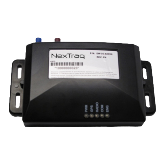
Appendix A – Technical Specifications The VT-2300 GPRS device is the latest hardware component from NexTraq that enables vehicle location and tracking through the NexTraq™ platform. The VT-2300 provides enhanced functionality through the support of Starter Interrupt, Driver ID, and Temperature Sensors. - Page 21 GSM/GPRS Modem Accessories The VT-2300 uses a quad-band GSM modem for The VT-2300 has cabling available for maximum network compatibility. standard installation needs. The possible accessories include: Driver ID with 1-Wire protocol Frequency Bands 850/900/1800/1900 MHz GPRS Class 12 max...
-
Page 22: Appendix B - Garmin Device Installation Notes
NOTE: The current standard Garmin PND model for Dispatch service is the Nuvi 1300 (U.S. data only). Other Garmin models are also compatible with the VT-2300 including the Nuvi 1350 (North America data) and certain over-the-road trucking models. A complete list of compatible models is available at http://www8.garmin.com/solutions/pnd/supportedproducts.jsp. - Page 23 Verify with NexTraq Customer Service that the Garmin PND is operational and communicating with the application. Call NexTraq Customer Service at 800.358.6178 for post-installation verification. Customer Service Hours: Monday-Friday 7:00am to 11:00pm (Eastern Time) Saturday-Sunday 7:00am to 3:00pm (Eastern Time)
-
Page 24: Appendix C - 1-Wire Device Installation Notes
• Key Fob Buzzer (DW-00-M0042) From the VT-2300 Adapter Cable, the Key Fob Reader uses the connector with green (PIN1) and black (PIN6) wires. Key Fob Buzzer uses the connector with blue and white (PIN5) and black (PIN6) wires. The Key Fob Reader should be placed in an easily accessible area for the driver. The key fob buzzer can be placed at the installer’s discretion. - Page 25 send a message to the web application indicating that the the driver associated with the iButton's ID number has turned on the vehicle's ignition. NOTE: A customer may order an LED light instead of the Key Fob Buzzer. The light is wired in the same manner as the buzzer.
- Page 26 • VT-2300 Adapter Cable (DW-00-M0047) The Temperature Sensing Probe connects to the VT-2300 6-pin Adapter Cable using the 2 pin connector with green (PIN1) and black (PIN6). Additional cable may be added for effective placement of the probe. However, the total length of the cable should not exceed 50 feet.
- Page 27 Temperature Sensor Wiring Diagram Installation of Automatic Drive ID and Temperature Sensor on one mobile unit When installing more than one 1-Wire device on the same VT-2300, follow the wiring diagram below for correct connections. NOTE: If the installation is to include both the Temperature Sensor and Automatic Driver ID, connect the red and black Extension Adapter Cable to the green (PIN1) and black (PIN6) wires from the 6-pin Adapter Cable.
- Page 28 Wiring Diagram for 1-Wire Device Combination Installation: Automatic Driver ID plus Temperature Sensor Verify with NexTraq Customer Service that the Automatic Driver ID and Temperature Sensor are operational and displaying information in the web application. Call NexTraq Customer Service at 800.358.6178 for post-installation verification.
-
Page 29: Appendix D - Starter Interrupt Installation Notes
• Starter Interrupt Relay (DW-00-M0049) Using the VT-2300 Adapter Cable, cut the orange and white (PIN4) wire from the 4-pin connector and strip it. Then connect the orange and white wire to the orange wire of the Starter Interrupt Relay. - Page 30 The VT-2300 mobile unit is not asserting control of the relay, thus the connection to the vehicle's starter is not interrupted and turning on ignition engages the starter for normal vehicle operation. On State – Starter Interrupt Active The starter Interrupt is turned on/activated by a special command issued from the Web Application.
- Page 31 Starter Interrupt Wiring Diagram...
- Page 32 Once the interrupt signal is sent from the NexTraq application and received by the mobile device, the relay will emit an audible click. After the signal is received, power to the ignition is denied. The vehicle will not start on next start attempt.
Need help?
Do you have a question about the VT-2300 and is the answer not in the manual?
Questions and answers