
Subscribe to Our Youtube Channel
Summary of Contents for Bollhoff RIVCLINCH 0201 FS
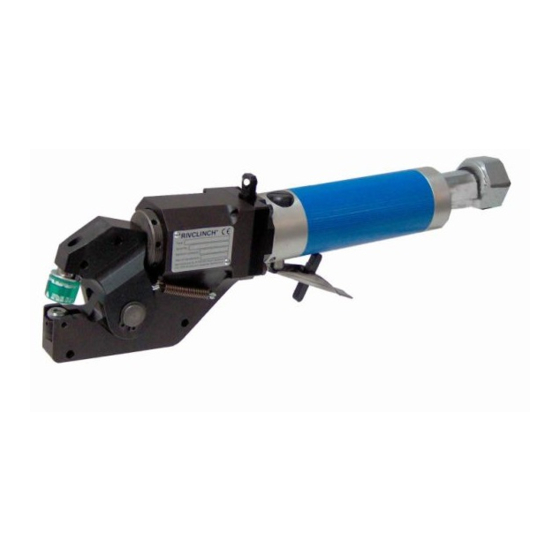
- Page 1 Bollhoff Attexor SA ® RIVCLINCH 0201 FS User manual Original edition in english Copyright © 2014 by Bollhoff Attexor S.A. Edition date: 2015-05-07...
-
Page 2: Copyright And Trademarks
Bollhoff Attexor S.A. disclaims all warranties either express or implied, including but not limited to, implied warranties of merchantability or fitness for a particular purpose of applications and hardware. In particular Bollhoff Attexor S.A. takes no responsibility of the performance of the joints on finished products. -
Page 3: Table Of Contents
..................24 ETTING THE REFERENCE VALUE ................... 25 INDING THE OPTIMUM SETTING ......................26 UALITY CONTROL 1 ..........................27 ABLE 2 ..........................28 ABLE 3 ..........................29 ABLE FIGURES ..........................30 Copyright © 2010 by Bollhoff Attexor S.A. Page 3... - Page 4 AFETY CABLE FOR BOOSTER INSTALLATION . 9. R ..........40 IGHT ORIENTATION OF THE RECESS ON THE DIE SET . 10. B ......................41 OOSTER . 11 P ..................42 NEUMATIC DIAGRAMME Copyright © 2010 by Bollhoff Attexor S.A. Page 4...
-
Page 5: Warranty
• Intervention on customer’s site or outside of our workshop • Failures resulting from sudden impact or obvious abuse Note, the use of other than original spare parts or accessories approved by Bollhoff Attexor may damage or reduce the performance of your product and may render the warranty void. -
Page 6: Warnings
• Always use protective gloves when operating the machine. • Always use hearing protector when operating the machine (noise level up to 80 dB). • Always wear safety shoes when operating the machine Copyright © 2010 by Bollhoff Attexor S.A. Page 6... - Page 7 • Never make a joint if the punch and the die are not covering 100% the sheet metal surface on both sides. In case of more than two sheet metal layers, make sure that the internal layers are also covering 100% of the joint area. Copyright © 2010 by Bollhoff Attexor S.A. Page 7...
- Page 8 Bollhoff Attexor. • Machines should be checked periodically to ensure that the ratings and markings are legibly marked on the machine. Contact your distributor or Bollhoff Attexor for replacement labels, if needed. Copyright © 2010 by Bollhoff Attexor S.A.
- Page 9 Bollhoff Attexor from all product liability claims and make Bollhoff Attexor's warranty null and void. Such an intervention also nullifies the CE-mark and Declaration of Conformity for machines originally delivered with such documents.
-
Page 10: Technical Specifications
Air preparation unit No 1, ½'', with filter, without lubricator Tool kits: various combinations of dies and punches of type SR403 and ST332 Rotator (rotating suspension ) Balancer For further information, consult the spare parts list. Copyright © 2010 by Bollhoff Attexor S.A. Page 10... -
Page 11: Functional Description
The clinching method used by this RIVCLINCH machine is based on a single-stroke method, patented or patents pending world-wide by Bollhoff Attexor S.A. 1. In the first part of the process, the punch will deform the overlapping sheet material plastically inside a die cavity. The wall of the die, typically split in two, three or four parts, remains closed. -
Page 12: Clinching System, End-Of-Stroke Control
Refer to chapter “Tooling selection and joint optimization” and Fig. 7 for instructions about adjusting the end stop. Copyright © 2010 by Bollhoff Attexor S.A. Page 12... -
Page 13: Installation, Connections
• Installing the booster and the workhead in a place where the lighting is at least 300 lux so as to check the oil level and to work in good conditions. Copyright © 2010 by Bollhoff Attexor S.A. Page 13... -
Page 14: Connection
6 bar (87 psi). As a rule, the working pressure should be adjusted 0.5 bar above the minimum required pressure for obtaining the correct joint, to be determined by testing. Copyright © 2010 by Bollhoff Attexor S.A. Page 14... -
Page 15: Start-Up
• Do not remove the sheets from the die, pulling laterally as that may damage the moving parts • Do not attempt clinching on surfaces that are not flat or where clinching has already been made Copyright © 2010 by Bollhoff Attexor S.A. Page 15... -
Page 16: Using Of The Clinching Machine
• When the cycle is finished, release the trigger. When there are several clinching points on the same flange, be careful that there are enough distance between points in order not to touch other points during the clinching cycle. Copyright © 2010 by Bollhoff Attexor S.A. Page 16... -
Page 17: Care And Maintenance
• Check the hydraulic connections. Do not tighten excessively the connection in aluminum between the booster (C1) and the hydraulic hose. Maximum torque for this connection is 20 Nm Copyright © 2010 by Bollhoff Attexor S.A. Page 17... -
Page 18: Oil Change
• Put back rapidly the plug (A10) and tighten it • Check the level (C2) and fill up if needed The machine is now ready for operating and the supply line (E1) may be connected again. Copyright © 2010 by Bollhoff Attexor S.A. Page 18... -
Page 19: Procedure For Bleeding Air From The Hydraulic Circuit
Check that the plug (C3) is well in place, that the oil level does not go beyond the max mark (C2) and the plug (A10) is well tightened and fitted with its seal. Not following these instructions may lead to disagreeable oil squirts. Copyright © 2010 by Bollhoff Attexor S.A. Page 19... -
Page 20: Replacing Wear Parts
In case of replacing the die blades, check the orientation of the blades according to Fig. 9. A wrong positioning (upside down) may significantly affect the point quality and the lifetime of the die. Copyright © 2010 by Bollhoff Attexor S.A. Page 20... -
Page 21: Replacing The Punch-Stripper Set
Do not force the punch or push it sideways during the disassembly. Always check upon reassembly that punch and die types correspond exactly to the tool kit selected for the application. Copyright © 2010 by Bollhoff Attexor S.A. Page 21... -
Page 22: Tooling Selection And Joint Optimization
Jm value which is equal to or smaller than the material thickness on the die side. A leak proof ST tooling is available on request, notables for the cases of 3 layers, such as with ventilation clinching. Ask your distributor for more detail. • Geometry Copyright © 2010 by Bollhoff Attexor S.A. Page 22... -
Page 23: Choice Of Stripper
The following chapter deals with criteria for judging the quality of the joints produced. It may be necessary to carry out tests with other tools or opting for other St values than those indicated in the tables. Copyright © 2010 by Bollhoff Attexor S.A. Page 23... -
Page 24: Adjusting The End Stop
• Maintaining the trigger activated, measure the distance H, as shown on Fig. 7b • Adjust, if necessary the end stop (A8) until the H value is 29.0 mm (release the trigger while turning the end stop) • Turning clockwise to increase H Copyright © 2010 by Bollhoff Attexor S.A. Page 24... -
Page 25: Finding The Optimum Setting
• Due to the elasticity, one step between 2 pin holes will be less than 0.12 mm under load • Repeat the process until the desired St value is obtained • Do not forget to re-tighten the locking screw (A31) Copyright © 2010 by Bollhoff Attexor S.A. Page 25... -
Page 26: Quality Control
• Punch diameter loss exceeding 0.1mm • Die spring damaged (can be replaced) • Die cage damaged or deformed in such a way that the die blades do not move properly Copyright © 2010 by Bollhoff Attexor S.A. Page 26... - Page 27 (fig.2) (fig.1) * and ferritic stainless steel, and copper For copper joining, the end stop adjusting is different of mild steel adjusting Fig.1 : Punch SR Fig.2 : Die SR 403 Copyright © 2010 by Bollhoff Attexor S.A. Page 27...
- Page 28 ST 332 12 (fig.2) * and ferritic stainless steel, and copper For copper joining, the end stop adjusting is different of mild steel adjusting Fig.1: Punch ST 30x30 Fig.2: Die ST 332 Copyright © 2010 by Bollhoff Attexor S.A. Page 28...
- Page 29 ST 312 10 (fig.2) 3 924 2717 014 ST 312 12 (fig.2) * Punch with special coatin Z1 Fig.1: Punch ST 30x30 Fig.1: Punch ST 30x30 Fig.2: Die ST 312 Copyright © 2010 by Bollhoff Attexor S.A. Page 29...
-
Page 30: Figures
ATTEXOR Clinch Systems SA User manual Figures Copyright © 2010 by Bollhoff Attexor S.A. Page 30... - Page 31 ATTEXOR Clinch Systems SA User manual Fig. 1. Main dimensions Copyright © 2010 by Bollhoff Attexor S.A. Page 31...
- Page 32 ATTEXOR Clinch Systems SA User manual Fig. 2. Various components and functions A3/A4 Copyright © 2010 by Bollhoff Attexor S.A. Page 32...
- Page 33 D. Suspension E. Supply Inlet air hose with valve with fast purging Pressure regulator and filter / water separator Air feeding hose for the booster Quick coupling without check valve F. Tooling Copyright © 2010 by Bollhoff Attexor S.A. Page 33...
- Page 34 ATTEXOR Clinch Systems SA User manual Fig. 3. Oil change Copyright © 2010 by Bollhoff Attexor S.A. Page 34...
- Page 35 ATTEXOR Clinch Systems SA User manual Fig. 4. Oil refill after complete drainage Copyright © 2010 by Bollhoff Attexor S.A. Page 35...
- Page 36 ATTEXOR Clinch Systems SA User manual Fig. 5. Removing the die-anvil set Copyright © 2010 by Bollhoff Attexor S.A. Page 36...
- Page 37 ATTEXOR Clinch Systems SA User manual Fig. 6. Removing the punch-stripper set A1 / A2 Copyright © 2010 by Bollhoff Attexor S.A. Page 37...
- Page 38 ATTEXOR Clinch Systems SA User manual Fig. 7. Adjusting the end-of-stroke, H and St values - St Ho = 29.0 Copyright © 2010 by Bollhoff Attexor S.A. Page 38...
- Page 39 ATTEXOR Clinch Systems SA User manual Fig. 8. Safety cable for booster installation Copyright © 2010 by Bollhoff Attexor S.A. Page 39...
- Page 40 ATTEXOR Clinch Systems SA User manual Fig. 9. Right orientation of the recess on the die set Copyright © 2010 by Bollhoff Attexor S.A. Page 40...
- Page 41 ATTEXOR Clinch Systems SA User manual Fig. 10. Booster Copyright © 2010 by Bollhoff Attexor S.A. Page 41...
- Page 42 ATTEXOR Clinch Systems SA User manual Fig. 11 Pneumatic diagramme Copyright © 2010 by Bollhoff Attexor S.A. Page 42...
Need help?
Do you have a question about the RIVCLINCH 0201 FS and is the answer not in the manual?
Questions and answers