
Subscribe to Our Youtube Channel
Summary of Contents for Deister electronic LCA 500
- Page 1 LCA 500 Wiring and Installation Instructions www.deister.com preliminary_fcc_lca-500_manual_en_896322_v200428_rev_3.docx...
- Page 2 Regulatory Notices Hereby, deister electronic declares that the radio equipment type LCA 500 is in compliance with Directive 2014/53/EU. The full text of the EU declaration of conformity is available at the following internet address: http://go.deister.com/ce Approved for use in all European countries.
- Page 3 Disclaimer deister electronic GmbH is not able to supervise the observance of the instructions given in this manual as well as the conditions and methods used during installation, operation and maintenance of the electronic devices and components respectively. Therefore we disclaim liability and reject responsibility for any losses, damages or costs that are caused by misap- plication, installation, handling errors or faulty operation or related to the above in any other way.
-
Page 4: Table Of Contents
Content 1. General Information ................5 2. Technical Data ..................5 3. Mechanical Dimensions ................6 LCA 500 .................................. 6 4. Connectors ..................... 7 5. Description of Connectors and Switches ..........8 I/O Connector ............................... 8 RS-485 IN Connector ............................8 RS-485 OUT Connector ............................. -
Page 5: General Information
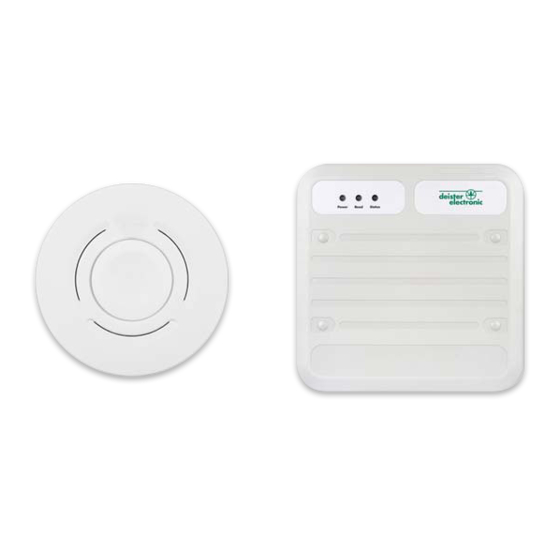
1. General Information The locator LCA 500 is a major component in the amanTag Human and Asset-Protection System. It simultaneously receives and processes the signals of the amanTag Transponders. It transmits a constant wake-up signal with a location code up to a range of 5 m. -
Page 6: Mechanical Dimensions
3. Mechanical Dimensions 3.1 LCA 500 All dimensions in mm [inch] For LED explanation, see chapter 6. preliminary_fcc_lca-500_manual_en_896322_v200428_rev_3.docx... -
Page 7: Connectors
4. Connectors Mainboard Connector I/O Connector RS-485 IN Connector RS-485 OUT Connector Terminal-Board LCA 500 Terminal/Mainboard Connector RS-485 Termination Switch Mainboard LCA 500 preliminary_fcc_lca-500_manual_en_896322_v200428_rev_3.docx... -
Page 8: Description Of Connectors And Switches
5. Description of Connectors and Switches 5.1 I/O Connector Symbol Description Input: positive contact Input: negative contact Relay 2 normal open contact Relay 2 common contact COMMON Relay 2 normal close contact Relay 1 normal open contact Relay 1 common contact COMMON Relay 1 normal close contact 5.2 RS-485 IN Connector... -
Page 9: Rs-485 Terminator Switches
5.5 RS-485 Terminator Switches Termination can be activated by flipping the termination switch to the “ON” position. This must be done if the device is on either end of the bus. Most RS-485-buses require termination resistors across the conduc- tor pair. The need for termination has to be checked for each installation. Especially for high data rates or long cables, the resistors are absolutely necessary. -
Page 10: Configuration Via Deisterconfig
200ms, when a transponder has been read (this may be changed in configuration). All signalization devices are configurable. Configuration via DeisterConfig Autotrim is automatically triggered on every startup of the reader. Connect the LCA 500 to a communication adapter (e.g.: SNG 3). • Connect the communication adapter to a PC. •... -
Page 11: Device Info
The configuration data of the device is loaded from the device and will be displayed: Device Info Field Device Info contains information about the device: preliminary_fcc_lca-500_manual_en_896322_v200428_rev_3.docx... -
Page 12: Basic Setup
Basic Setup The following parameters may be changed from the Basic Setup panel: Field ID: Changing the Field ID is only necessary, if more than one device is mounted within the • Radio Range of the transponders. This requires the field ID to be unique. Reading range control: This will adjust the read range from 10% to 100% •... - Page 13 If the external triggering is deactivated again, the locator must be restarted after saving in order for the option to be accepted. preliminary_fcc_lca-500_manual_en_896322_v200428_rev_3.docx...
-
Page 14: Firmware Update Via Deisterconfig
7. Firmware update via DeisterConfig Connect the locator to a communication adapter (e.g.: SNG 3). • Connect communication adapter to a PC. • Supply locator with DC Voltage in the range of 12…24V. • Launch DeisterConfig.exe. • The following start screen appears: The content of the start screen depends on the connected devices. - Page 15 The configuration data of the device is loaded from the device and will be displayed: In order to update the firmware of the device, select Update firmware from the menu Device. Select the folder where the firmware is stored. After double clicking on the file, the update process starts: After the firmware is updated successfully, the following dialog appears: preliminary_fcc_lca-500_manual_en_896322_v200428_rev_3.docx...
-
Page 16: Installation Instructions
(GND) of the power supply. Field Characteristics The following diagram shows the read range of the LCA 500. Please note that the read range varies de- pending on the position of the transponder as shown in the diagram below. The presence of any magnetic material such as steel changes the given shape. -
Page 17: Do´s And Don'ts
9. Do´s and don’ts Do not place transponder in short circuit coil or Install transponder in front of or behind the short- in metal frame! circuit coil or metal! Do not install reader directly on metal! One meter distance to a metal sheet results in a ne- glectable effect on the field. - Page 18 (Hz) Do not use near devices that interfere in the range No interference in the range of 125 kHz / 868 MHz of 125 kHz / 868 MHz (e.g., old forklifts). guarantees optimal performance. The signal energy of one reader interferes with the The signal energy from one reader does not inter- read/write range of another.
- Page 19 Notes: preliminary_fcc_lca-500_manual_en_896322_v200428_rev_3.docx...
- Page 20 Fax: +33 (0) 1 47 – 35 92 59 info.us@deister.com info.fr@deister.com Singapore: Great Britain: Coselec Pte Ltd. deister electronic (UK) Ltd. Blk 28 Kallang Place Stapleton Way, Enterprise Park #06-12/14, Singapore Spalding, Lincolnshire 339158 PE11 3YQ Tel.: +65 6741 5200 Tel.:...
Need help?
Do you have a question about the LCA 500 and is the answer not in the manual?
Questions and answers