
Related Manuals for Sub-Zero Wolf CE Series

Summary of Contents for Sub-Zero Wolf CE Series
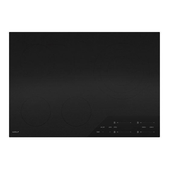
- Page 1 subzero.com 800.222.7820 CE Electric Cooktop Service Manual General Information Controls & Operation Component Access & Removal Troubleshooting Guide Technical Data Wiring Diagrams...
-
Page 2: General Information
Sub-Zero Group, Inc. Neither this manual nor any information or images contained herein may be copied or used in whole or in part without the express written permission of Wolf Appliance, Inc., an affiliate of Sub-Zero Group, Inc. © Wolf Appliance, Inc., all rights reserved. -
Page 3: Warranty Information
Cooktop Electric (CE) Series Cooktop Electric (CE) Series General Information WARRANTY INFORMATION This page contains a summary of the 2 & 5 Year Warranty that is supplied with every Wolf product, followed by a Non-Residential Warranty Summary and then notes about the warranties. 2 &... - Page 4 Cooktop Electric (CE) Series Cooktop Electric (CE) Series General Information COOKTOP FEATURES MODEL NUMBER KEY • Two styles Refer to this key for an example of the model numbers. • Transitional Series - stainless steel trim. • Contemporary Series - black unframed. •...
- Page 5 Cooktop Electric (CE) Series Cooktop Electric (CE) Series General Information CE SERIES CONFIGURATIONS 30” Four Element Assemblies - Contemporary 30” Four Element Assemblies - Transitional Model Number: CE304C/B Model Number: CE304T/S Description: Cooktop Electric, 30”, Four Element Description: Cooktop Electric, 30”, Four Element Assemblies, Contemporary / Black unframed Assemblies, Transitional / Stainless steel 36”...
- Page 6 Electronics Cooktop Electric (CE) Series Cooktop Electric (CE) Series ELECTRONICS This section describes the basic operation of the CE Series electronics and how the touch pad responds to input commands. The control board receives touch sensitive input and triggers a command in the power board. The power board uses triacs and relays to maintain the correct power at the element assembly.
- Page 7 Cooktop Electric (CE) Series Electronics Cooktop Electric (CE) Series Frequency Duration and Selection Chart Name Duration Type Occurrence Valid Selection 280 ms Beep Touch on valid pad Invalid Selection 750 ms Beep Touch on invalid pad Acceptance 280 ms Beep Twice with 250 ms delay on the successful receipt of a command Four times with 200 ms delay on the expiration of a timer Timer Complete...
- Page 8 Electronics Cooktop Electric (CE) Series Cooktop Electric (CE) Series 2200 Watts 2700 Watts 1800 Watts 1950 Watts 1600 Watts - 208 700 Watts 1050 Watts Bridge 4400 Watts 3800 Watts - 208 1800 Watts 1600 Watts - 208 1200 Watts Timer General Information: •...
- Page 9 Cooktop Electric (CE) Series Electronics Cooktop Electric (CE) Series Ending the Timer: • At 60 seconds the One Minute Remaining beep sounds. • At 00 the Timer Complete beep sounds until acknowledged. • Touch of the TIMER or “-” pad stops Timer Complete beep and clears the display. •...
- Page 10 Electronics Cooktop Electric (CE) Series Cooktop Electric (CE) Series Valid key presses in Lock Mode: • LOCK pad for exiting Lock Mode. • Touch and hold “+” and “-” pads for 5 seconds to enter Diagnostic Mode. Display states in Lock Mode: •...
- Page 11 Cooktop Electric (CE) Series Electronics Cooktop Electric (CE) Series Operational Mode When any control zone is active at any power level greater than 0. Entering Operational Mode from Wake-Up Mode: • SIM or MLT – Activates the control zone at power level 1. •...
- Page 12 Electronics Cooktop Electric (CE) Series Cooktop Electric (CE) Series ALL OFF: • De-energizes the entire cooktop at any time. • Does not turn off the TIMER. Error Mode: Note: For error codes see Section 4 - Troubleshooting. • System logs initial generation of an error into memory for later inspection. •...
- Page 13 Cooktop Electric (CE) Series Electronics Cooktop Electric (CE) Series Diagnostic Mode Used to test the cooktop systems, view stored error codes, view real-time readings from system sensors, and to enter/exit Showroom mode. Individual element assembly temperature readings are not available for CE models. Entering Diagnostic Mode: •...
- Page 14 Electronics Cooktop Electric (CE) Series Cooktop Electric (CE) Series Element Temperature: Built-in Thermal Limiter: • Each element has a built-in thermal limiter to protect the glass top. • Thermal limiter will open between 1040° F and 1076° F. • Thermal limiter will close at approximately 950° F. Error Code Indicator •...
- Page 15 Cooktop Electric (CE) Series Electronics Cooktop Electric (CE) Series User Options Mode Entering User Options Mode • Cooktop must be in Idle Mode. • Touch and hold ALL OFF pad for 5 seconds. • After 5 seconds a valid selection beep sounds alerting the user to remove their finger. •...
-
Page 16: Component Removal
Cooktop Electric (CE) Series COMPONENT REMOVAL This section explains how to remove components from a Wolf CE Series. Depending on which component you are going to remove, you may have to remove other components first. Refer to the appropriate section in this manual that explains how to remove those various components. -
Page 17: Glass Top
Cooktop Electric (CE) Series Component Removal Cooktop Electric (CE) Series Glass Top To remove the glass top, first remove the cooktop from the installation, then (See Figure 3-1): 1. Use a Phillips screw driver or a 1/4” nut driver to extract screws from front frame. -
Page 18: Wire Harness
Component Removal Cooktop Electric (CE) Series Cooktop Electric (CE) Series Control Board To remove the control board, first remove the glass top, Bracket then (See Figure 3-3): Cover Screws 1. Use a Phillips screw driver to extract the screws from the control board bracket. 2. - Page 19 Cooktop Electric (CE) Series Component Removal Cooktop Electric (CE) Series To remove the fan assembly, first remove the power board bracket, then (See Figure 3-5): 1. Press connector tab in and disconnect fan assem- bly connector from power board. 2. Use a small flat blade screw driver to spread the fan assembly retainer tabs slightly to release fan assembly.
-
Page 20: Troubleshooting
TROUBLESHOOTING This section of the manual contains troubleshooting information which will help the Certified Service Technician trou- bleshoot a Wolf CE Series. The table of contents below shows how the troubleshooting section is laid out. ELECTRIC Power board and control board share the software for controlling the cooktop. If a logic or programing issue is sus- pected replace the control board first as it is the less expensive part. - Page 21 Cooktop Electric (CE) Series Troubleshooting Cooktop Electric (CE) Series Diagnostic Mode Used to test the cooktop systems, view stored error codes, and to enter/exit Showroom mode. Entering Diagnostic Mode Enter Lock Mode. Touch and hold the “+” pad and “-” pad for 5 seconds. •...
- Page 22 Troubleshooting Cooktop Electric (CE) Series Cooktop Electric (CE) Series Element Temperature Test Touch “+” pad during the Heat Sink Temperature Test. • Five “.” displayed on left rear control zone. • 2-digit display shows 00, but is not active on CE models. “-”...
- Page 23 Cooktop Electric (CE) Series Troubleshooting Cooktop Electric (CE) Series General Errors Table Code Test Description Action Pad Error None 1. Cycle unit power. 2. Reseat Low Voltage (LV) Wire Harness. 3. Replace control board. Data Flash Error 1. Cycle unit power. None (result of flashing software) 2.
- Page 24 Troubleshooting Cooktop Electric (CE) Series Cooktop Electric (CE) Series Cooking Zone Specific Errors Code Test Description Action Relay error None 1. Cycle unit power 2. Replace power board. Power supply error 1. Inspect all power supply 1. L1 to Ground and L2 to Ground connections.
- Page 25 Cooktop Electric (CE) Series Troubleshooting Cooktop Electric (CE) Series Fan Test Each power board has a 12 VDC fan. It is not possible to check the fan by measuring the resistance. Fan resist- ance is never constant so is not measurable. Use a 9 volt battery to energize the fan.
-
Page 26: Technical Data
Cooktop Electric (CE) Series Cooktop Electric (CE) Series Technical Data • THIS APPLIANCE MUST BE PROPERLY GROUNDED AT ALL TIMES WHEN ELECTRICAL POWER IS APPLIED. • DO NOT GROUND APPLIANCE WITH NEUTRAL (WHITE) HOUSE SUPPLY WIRE. A SEPARATE GROUND WIRE MUST BE UTILIZED. •... - Page 27 Cooktop Electric (CE) Series Cooktop Electric (CE) Series Technical Data 36” Electric Power Level - Single Zone, 2-Zone, and Bridge 700 W 2200 W 1800 W 800 W LEDs 1200 W Operation Level % of Power Element Element Element Element Displayed Element Limit...
- Page 28 Cooktop Electric (CE) Series Cooktop Electric (CE) Series Technical Data Element Assembly Wattage, Diameter, and Resistance 1200 Watts 240 VAC 1200 Watts Total Diameter Cold Total Diameter Cold Wattage (inches) Resistance Wattage (inches) Resistance (± 5%) (± 5% Ohms) (± 5%) (±...
- Page 29 Cooktop Electric (CE) Series Cooktop Electric (CE) Series Technical Data 2700 Watts 240 VAC Total Diameter Zone 1 Zone 2 Zone 3 Wattage (inches) Wattage Cold Wattage Cold Wattage Cold (± 5%) (± 5%) Resistance (± 5%) Resistance (± 5%) Resistance (±...
- Page 30 Wiring Cooktop Electric (CE) Series Cooktop Electric (CE) Series WIRE DIAGRAM MODEL: CE30 - This wiring information is provided for use by qualified service personnel only. - Disconnect appliance from electrical supply before begining service. - Be sure all grounding devices are connected when service is complete. - Failure to observe the above warnings may result in severe electrical shock.
- Page 31 Cooktop Electric (CE) Series Wiring Cooktop Electric (CE) Series WIRE DIAGRAM MODEL: CE36 - This wiring information is provided for use by qualified service personnel only. - Disconnect appliance from electrical supply before begining service. - Be sure all grounding devices are connected when service is complete. - Failure to observe the above warnings may result in severe electrical shock.
Need help?
Do you have a question about the Wolf CE Series and is the answer not in the manual?
Questions and answers