
Related Manuals for FE PXR3

Summary of Contents for FE PXR3
- Page 1 Digital Thermostat PXR3 °C SET1 SET2 (Replacement for PAS3) Type: PXR3 Operation Manual INP-TN5A2886-E...
-
Page 2: Table Of Contents
Table of Contents 1 Display and Keys........................4 2 Operation..........................5 2-1 Parameter List ......................... 5 2-2 Basic Operation ....................... 7 2-3 Parameter Functions and Method of Settings ..............9 Level 1 parameters (operation mode) ................9 PV display ........................9 Alarm 1 setpoint (SET1) display ................. - Page 3 Table 1: Model Codes Sensor Range Alarms Model PXR3TAY2-0Y061 Thermocouple See Table 2 PXR3TAY2-1Y061 PXR3HAY2-0Y061 Thermistor 0–100°C PXR3HAY2-1Y061 Notes 1. You cannot switch between thermocouple input and thermistor input. 2. Default settings are as follows: Thermocouple version: type K thermocouple, 0–1200°C range Thermistor version: thermistor input, 0–100°C range *If you ordered a thermocouple version, you can change the input setting to the one for other thermocouples as shown in...
-
Page 4: Display And Keys
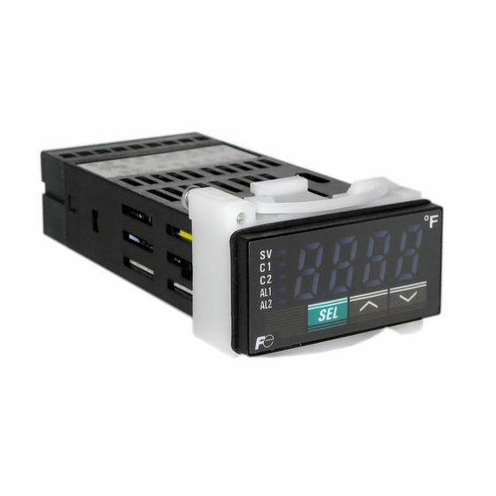
Display and Keys ⑦ Display ⑥ Unit indicator Process value (PV) indicator ① °C Alarm 1 set value (SET1) indicator ② SET1 Alarm 2 set value (SET2) indicator ③ SET2 Alarm 1 (AL1) indicator ④ Alarm 2 (AL2) indicator ⑤ ⑩ key ⑨ key ⑧ key... -
Page 5: Operation
Operation Parameter List Level Description Notes Level 1 Process value and alarm setpoint You cannot change the alarm (indication only) setpoint in Level 1. Level 2 Alarm setpoint change Level 3 Set up Level 4 Input compensation Level 1 Parameters Your Function Name... - Page 6 Level 4 Parameters Your Function Name Range Default setting Page setting Allows you to set the time constant. Input filter time 0.0-90.0 s *Setting is available in 0.5 seconds constant increments. Setting to “0.0” turns off the filter. Allows you to shift the process value (PV) PV offset -10% to 10% FS °C...
-
Page 7: Basic Operation
Basic Operation When you turn on the digital thermostat, the screen shows “– – – –“ and then the process value. °C SET1 SET2 Display mode switching Operation mode (level 1) Process value (PV) display Alarm 1 set value (SET1) display Alarm 2 set value (SET2) display Press once... - Page 8 Parameter setting Set value display <Parameter setting procedure> 1) Select a parameter you want to set °C by pressing the key. SET1 SET2 2) Press the key to display the parameter set value. 3) Press the key, to change the parameter set value. 4) To save the change, press the Blink key or just wait for 3 seconds.
-
Page 9: Parameter Functions And Method Of Settings
Parameter Functions and Method of Settings Level 1 parameters (operation mode) °C SET1 SET2 PV display °C SET1 SET2 Alarm 1 setpoint (SET1) display °C SET1 SET2 Alarm 2 setpoint (SET2) display ————————————————————————————————————————————— Related parameters: (page 10), (page 10) [Examples] ——————————————————————————————————————— PV display °C SET1... -
Page 10: Level 2 Parameters
Level 2 parameters Alarm 1 setpoint (SET1) setup Alarm 2 setpoint (SET2) setup ————————————————————————————————————————————— (range lower limit) and (range upper limit). Related parameters: (page 12), (page 12), (page 13), (page 13) [Setting example] Changing the alarm 1 setpoint from 1200°C to 700°C ——————————— Display Operating procedure Press the... -
Page 11: Level 3 Parameters
Level 3 parameters Input type ————————————————————————————————————————————— K thermocouple, change the setting of this parameter according to the type of thermocouple you use, in reference to Table 3. If you change the input setting, do not forget to change the range setting ( and ... -
Page 12: Range Lower Limit Setup
“Pn2” to “3”, the PSL should be “0” and the PSU should be “1200”. ” and “ ” do not appear on the PXR3 thermistor input version (5th code “H”). PSL is and/or , check out the values of the following parameters because they automatically... -
Page 13: Alarm Type 1
Absolute Relay Upper Without de-energization value limit Note: Be sure to power-cycle PXR3 after you change the alarm type. Relay Absolute Lower How to read activation diagram Without de-energization value limit area: Range in which the AL1 or the AL2 indicator lights. -
Page 14: Alarm 1 Hysteresis
————————————————————————————————————————————— Fig 1: Alarm Hysteresis Hysteresis = 10°C Hysteresis = 0°C Alarm ON Alarm ON Alarm OFF Alarm OFF 10℃ Alarm setpoint Alarm setpoint (SET1 or SET2) (SET1 or SET2) Note: details, see Page 24. [Setting example] Changing the alarm 1 hysteresis from 0°C to 10°C ———————————— Display Operating procedure Press the... -
Page 15: Alarm 1 On Delay Time
Alarm 1 ON delay time (setting range: 0 to 120 seconds) Alarm 2 ON delay time (setting range: 0 to 120 seconds) ————————————————————————————————————————————— starts. ( ① start. ( ③ ② in the Fig 2: Alarm ON Delay Alarm state Normal alarm action Alarm ON delay time Alarm action during alarm ON delay... -
Page 16: Burn-Out Direction
Burn-out direction (setting range: L or H) ————————————————————————————————————————————— Allows you to set how the input reacts if an input error such as open loop, under-range, or over-range is detected. setpoint Input value at input error Alarm setting Upper limit Upper limit alarm Lower limit Lower limit alarm Notes:... -
Page 17: Power On Delay Time
Power ON delay time (setting range: 0 to 120 seconds) ————————————————————————————————————————————— ① start. ( ③ ② in Fig 3: Power ON Delay Alarm state Normal alarm action Alarm action during Power ON delay ① ③ ② Power ON delay time Power ON delay time Notes: [Setting example] Setting the power ON delay time to 60 seconds —————————————... -
Page 18: Setup Lock
Setup lock (setting range: 0 to 2) ————————————————————————————————————————————— cannot edit. setting Description No lock. All the parameters can be edited. All the parameters are locked. Only the alarm setpoint 1 (SET1) and the alarm setpoint 2 (SET2) can be changed. Note: [Setting example] Setting the setup lock to “2”... -
Page 19: Level 4 Parameters
Level 4 parameters ————————————————————————————————————————————— displayed PV gradually changes, taking 5.0 seconds to change from 0°C to 63°C. Fig 4: Input Filter Input Alarm Input Alarm output filter judgment PV (°C) Actual input PV display Time (t) Note: — Display Operating procedure Press the key for 9 seconds. -
Page 20: Pv Offset
————————————————————————————————————————————— PV agree with the reading of a recorder. Note: ————— Display Operating procedure Press the key for 9 seconds. display appears. Use the keys to access Press the key once. The setpoint ( ) is displayed. Use the keys to change Press the key once. -
Page 21: User Zero Adjustment
————————————————————————————————————————————— these parameters to “0”. Zero point adjustment: Span point adjustment: Example when using the type K thermocouple whose input range is 0–1200°C If the reading for 0°C input is -8°C, and the reading for 1200°C input is 1206°C, you should set to “8”... -
Page 22: Alarm
Alarm type PXR3 has eight types of alarms. Select the right type for your application from the table below, and set the right code for your selection to the parameters (alarm type 1) and (alarm type 2). -
Page 23: Energization And De-Energization
Relay de-energization: Alarm relay contact is opened when an alarm occurs. The contact is closed during normal operation. Note that the contact is also opened during no power is supplied to PXR3 and during the initial action (“----“ is displayed) after power-up. Alarm setting... -
Page 24: Alarm Latch By Hysteresis
Fig 7: Upper Limit Alarm Latch latch, i.e. once the alarm starts to work, it will not go off even if the input goes out of the alarm range. To turn off the alarm, power-cycle PXR3 or change the Alarm alarm type of and/or to “0”. -
Page 25: Alarm On Delay Time
Alarm ON delay time Alarm ON delay functions for all the alarms including the input error alarms (open loop, over-range, and under- range). The alarm starts only after the delay time you set has passed. Fig 8: Alarm ON Delay Alarm state Time Time... -
Page 26: Troubleshooting
R thermocouple tends to show large error around the room temperature. The input sensor in use is not Use the right sensor for your PXR3 or the 2, 11 appropriate for the version of right PXR3 for the sensor you use. - Page 27 Set the alarm ON delay to 0, and check if is too large. the alarm occurs. The alarm type setting is Set the parameters inappropriate. appropriately in reference to the FALT appears on the PXR3 is failed. Stop the operation and consult us. – screen.
- Page 28 Index AL1, AL2 ................4 SEL key ................4 Alarm latch..............14, 24 SET1, SET2.................9 Alarm ON delay ..............15 Setup lock ................18 Alarm setpoint..............10 Span adjustment..............21 Alarm type .................13 Troubleshooting ..............26 Burnout direction ...............16 Under-range ............12, 16, 26 Calibration .................21 Unit indication ..............4 Up key .................4 User zero/span adjustment..........21 De-energization ............13, 23...
- Page 29 Caution on Safety *Before using this product, be sure to read its instruction manual. Global Sales Section Instrumentation & Sensors Planning Dept. 1, Fuji-machi, Hino-city, Tokyo 191-8502, Japan http://www.fujielectric.com Phone: +81-42-514-8930 Fax: +81-42-583-8275 http://www.fujielectric.com/products/instruments/ Information in this catalog is subject to change without notice. Printed in Japan...
Need help?
Do you have a question about the PXR3 and is the answer not in the manual?
Questions and answers