Table of Contents
Advertisement
Quick Links
Advertisement
Table of Contents

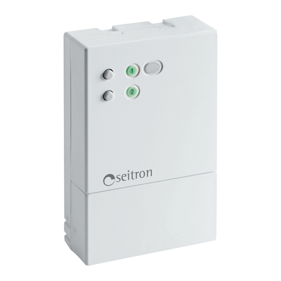
Summary of Contents for Seitron SwitchON
- Page 1 SwitchON SWITCH IoT WiFi RADIO RECEIVER 2,4GHz COMPLETE INSTRUCTION MANUAL...
-
Page 3: Table Of Contents
GLOSSARY Pairing: it is the procedure by which the SwitchON and the Seitron Smart App OR the SwitchON and a transmitter are coupled. MAC Address (Media Access Control): it is a unique ID code for a particular device (in this case, the SwitchON address). - Page 4 GS001M0000SE 034926 220720...
-
Page 5: Overview
Else, if the device is used as a radio receiver coupled with a transmitter, the SwitchON receives the commands that the transmitter sends out to it depending on necessities (e.g. if a SwitchON is connected to the boiler as a receiver and it is coupled with a wi-time, the latter sends out signals to the SwitchON depending on heat/cooling necessities of the room). -
Page 6: Electrical Wirng
WIRING DIAGRAM WARNING - If the load controlled by the SwitchON relay operates with mains voltage, the connections must be made via an omnipolar switch complying with current standards and with contact opening of at least 3 mm in each pole. -
Page 7: Switch Iot Operation Mode
SWITCH IOT OPERATION MODE With the SwitchON WiFi IoT mode (remote switch) it is possible, using the Seitron Smart app, to switch on and off two loads, one for each relay with which the product is equipped; the loads can be, for example, an irrigation system or an automatic garage door. -
Page 8: Manual Output Control
In order to switch on/off output OUT 2, it is necessary to shortly press the button Manual output control is possible even if the device has never been paired with Seitron Smart app or it has been erased. In this last case,... -
Page 9: Pairing
PAIRING This procedure consists of connecting the Seitron Smart app to your SwitchON; after which it will be possible to control the two relays (and consequently to control the relative loads) remotely. Make sure to move the jumper on IOT position: Switch IoT mode. - Page 10 Add a new SwitchON and connect it with the App. Press Press SwitchON ‘ ‘ ‘ ‘ The instructions that appear on the screen are the ones reported on the previous points; make sure to have them all done correctly and press the ‘Start’ button.
-
Page 11: Reset (Procedure)
RESET (PROCEDURE) In order to reset the device to default condition (reset procedure) it is necessary to disconnect the SwitchON from the Seitron Smart app so that the device is not visible on the app dashboard; to perform this procedure, proceed as follows: Access the Seitron Smart app;... -
Page 12: Radio Receiver Operation Mode
To a single SwitchON it is possible to pair up to a maximum of 6 wi-times (for further details see chapter “Example of logic wiring diagram”). It is possible to use only one receiver output, which can be chosen directly from the wi-time settings. -
Page 13: Example Of Logic Wiring Diagram
EXAMPLE OF LOGIC WIRING DIAGRAM Example of a system made up by three SwitchON on radio receiver mode and two wi-time: two SwitchON are controlling a zone solenoid valve each and they are receiving the inputs from the related paired wi-time, while the third SwitchON manages the inputs that both the wi-time are sending to it. - Page 14 Up to 6 wi-time can be paired to a single SwitchON connected to the boiler. Example of a system made up by six wi-time (maximum number of wi-time from which a single SwitchON can receive inputs) which send inputs to a SwitchON connected to a boiler; this system allows greater freedom about where to place the transmitters.
-
Page 15: Radio System Configuration
SLAVE position: receiver mode. Make sure that the SwitchON device is correctly powered; before installing the transmitter on its final location, check that the SwitchON correctly receives its signals. The SwitchON will not give information about radio signal strength; in order to check the radio communication between SwitchON and transmitter (wi-time), refer to the complete transmitter user manual. -
Page 16: Troubleshooting
When on radio receiver mode, the boiler or the load won’t switch on. PROBABLE CAUSE: The boiler or the load are connected to the wrong output. The SwitchON only manages one output, which is selected on the transmitter or there is no radio communication between the transmitter and receiver. - Page 17 GS001M0000SE 034926 220720...
- Page 18 SEITRON S.p.A. a socio unico Via del Commercio, 9/11. 36065 Mussolente (VI) ITALY +39 0424 567842 - http://www.seitron.com - e-mail: info@seitron.it...


Need help?
Do you have a question about the SwitchON and is the answer not in the manual?
Questions and answers