Table of Contents
Advertisement
Quick Links
Advertisement
Table of Contents

Related Manuals for Ikegami MKC-X800


Summary of Contents for Ikegami MKC-X800
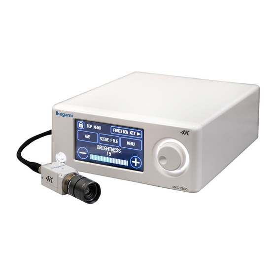
- Page 1 User Manual Digital Process Compact UHD Color Camera MKC-X800 Model...
- Page 2 This software is copyrighted by IKEGAMI TSUSHINKI CO., LTD. Unauthorized reproduction, modifications or alterations to this manual, whole or in part, is prohibited.
-
Page 3: Operating Precautions
Cautions when Operating Examples of Symbols Important Basic Precautions ● This symbol indicates an instruction and implementation of an action. (1) Please be sure there are no abnormalities or defects Specific examples of cautions are illustrated in the construction or function of this device. in the figure. - Page 4 When an abnormality is detected During installation If abnormal conditions, include smoke, a Do not block the vent of this device! strange odor or noise are observed, If the vent is blocked, heat may build up inside immediately turn off the power and unplug and cause a fire.
- Page 5 is damaged, contact the sales representatives for Cleaning replacement. ・For safety, turn off the power and remove the power plug During installation before cleaning. This may result in electric shock. ・Avoid areas with high humidity and dust, as well as ・Wipe lightly the enclosure and panel with a dry soft cloth.
- Page 6 Dispose this product in compliance with the laws and regulations of the municipality. Please consult with your municipality for details. MKC-X800 is an authorized AAMI ES60601-1/EN60601- 1 ClassⅠ product. The IP rating of MKC-X800 is IPX0. The MKC-X800 device is for continuous operation.
- Page 7 Guidelines and manufacturer's declaration - electromagnetic emissions The Model MKC-X800 is intended for use in the electromagnetic environment specified below. The customer or user of the Model MKC-X800 should confirm that the environment is in compliance. Emissions test Compliance Electromagnetic...
- Page 8 For25/30 cycle (30%dip ln Ut) operation times when the For25/30 cycle main power may be IEC61000-4-11 interrupted, powering the MODEL MKC-X800 with an uninterruptible power supply or battery is recommended. Power frequency 30 A/m 30 A/m The power frequency (50/60 Hz)
- Page 9 Guidelines and manufacturer's declaration - electromagnetic emissions The Model MKC-X800 is intended for use in the electromagnetic environment specified below. The customer or user of the Model MKC-X800 should confirm that the environment is in compliance. IEC 60601 test Compliance...
- Page 10 EMC information provided in the accompanying documents. Avoid using MKC-X800 next to or stacked with other equipment as this my result in inaccurate operation. If such cannot be avoided, it should be watched to confirm normal operations in configured use conditions.
-
Page 11: Table Of Contents
Table of Contents Operating Precautions ......................3 Safety Precautions ......................3 Introduction ....................... 15 Construction ....................... 15 Part Name and Functions of Parts ..................15 Camera Head........................ 15 CCU Front ........................16 CCU Back ........................17 Accessories ........................19 Operation (Basics) ...................... 20 Connection Example ...................... - Page 12 4.4.2 Contrast adjustment (CONTRAST) ................. 36 4.4.3 Color adjustment (COLOR) ................... 38 4.4.4 Sharpness adjustment (SHARPNESS) ..............39 4.5 Function (FUNCTION) ....................40 4.5.1 Scaling (MAGNIFIER)/Flip(FLIP) ................41 4.5.2 Assigning a function to a function key (FUCTION KEY) ..........42 4.5.3 Function assignment of TOP MENU indicator (TOP MENU INDICATOR) ......
- Page 13 Settings ........................66 3D support function ......................66 Connections and settings ....................66 Connecting the operation panel and the menu ..............68 Manually Setting a Metering Frame ..................68 Settings ........................68 5.12 Others ........................69 Scene File ........................70 Saving a Scene File ......................
- Page 14 CCU ..........................85 10 Troubleshooting ......................86 Common problems and solutions Start-up ................86 Error Message ......................... 89...
-
Page 15: Introduction
1 Introduction MKC-X800 is a 4K Camera equipped with high-definition 4K video (3840 × 2160) and color reproduction. It is a medical grade camera which can be used with a surgical microscope or shadow-less lamp system. MKC-X800 employs a 1 CMOS system, performs 3840 x 2160 4K format with 1800TV lines horizontal resolution, S/N ratio with 58dB. -
Page 16: Ccu Front
CCU Front ② ③ ① ① Power button The power button to turn MKC-X800 ON/OFF. ② Touch sensor panel The touch sensor panel displays the menu screen. Operation of menu screen is possible by touching the screen. ③ Rotary Switch The rotary switch is used to selecting settings and renaming scene files. -
Page 17: Ccu Back
CCU Back ① ① ① ① ② ③ ④ ⑤ ⑥ ⑪ ⑦ ⑧ ⑧ ⑨ ⑩ ⑫ ① 4K OUT connector(SDIx4) (12G-SDI) A UHD-SDI 2-Sample Interleave Level-A (3G-SDI Quad Link or 12G-SDI) input compatible monitor etc. can be connected here. When output is 4K 12G-SDI, the same video can be output to all four lines. 4K UHD coax cables for 12G-SDI (e.g. - Page 18 ⑦ DVI-D OUT connector This is the image output port A DVI-D input monitor, etc. can be used with a DVI-D cable with ferrite core (separately sold). Ferrite core ⑧ HD-SDI(3G-SDI) OUT connector (2 lines) An HD-SDI (3G-SDI)-input-compatible monitor etc. can be connected here. The same video is output to two lines. A coaxial cable with a 75 Ω...
-
Page 19: Accessories
Accessories Open the box and make sure the device and the following accessories are included. Camera cable (5m) × 1 ⚫ ⚫ Extension cable (10m) × 1 (Option) ⚫ Power cord × 1 ⚫ AC adapter ⚫ User manual (this document) ⚫... -
Page 20: Operation (Basics)
3 Operation (Basics) Connection Example 4K-Compatible monitor MKC-X800 camera head HDMI cable Foot switch Camera cable DVI-D cable 75Ω coaxial cable Power cable MDR-600HD DVI monitor ※ To connect a 4K monitor, follow the directions of the operation manual of the monitor. - Page 21 Notes on the Connection ・Be sure to turn off the main unit of camera before connecting. ・Connect a dedicated camera head. Connect a different head may result in a malfunction. ・Image output from the 3G/HD-SDI connector is on the receiving side with 75Ω terminal.
-
Page 22: Start-Up And Shut Down Of The Main Unit
Start-Up and Shut Down of the Main Unit Start-up and shut down methods for the main unit are explained in this section. Start-up method 【Step 1】Preparation before turning on power Before turning on power, check the following. ・Be sure the external devices including a camera head, monitor, etc. are properly connected. ・Be sure the power cable (accessory) is connected to the DC inlet of the CCU rear panel, and the plug of the power cable is connected to the commercial power outlet. -
Page 23: Step 3
【Step 3】 Press the power switch on the front panel of the CCU to turn on the power. When the power is on, the power switch indicator turns blue. Notes on the Camera Image Immediately after turning on the power, initialization of CCU or the camera head automatically begins. During this time, an unstable image is displayed on the monitor, this it is not a malfunction. -
Page 24: Checking The Camera Image
Notes when Moving the Device When moving the main unit, be sure to turn off the main power supply, unplug the power plug, and remove the connection cable between the devices. Notes when Connecting or Disconnecting the Camera Cable When connecting or disconnecting the camera cable connecting the camera head and CCU, be sure to turn off the power of the main unit. -
Page 25: Touch Panel Operation
Touch panel operation 3.3.1 TOP MENU ④ ② ⑤ ③ ① ① Direct adjustment with the touch panel or Rotary Switch. Up to three functions can be assigned to the [TOP MENU INDICATOR] screen (→4.5.3). The assigned functions can be selected from TOP MENU by pressing the Rotary Switch. ②... -
Page 26: Menu Screen
3.3.2 Menu screen ① ② ④ ③ ⑤ ⑥ ② Return to the previous screen. ③ Return to the TOP MENU. ④ Go to the PICTURE setting screen (→4.4). ⑤ Go to the FUNCTION setting screen (→4.5). ⑥ Go to the SYSTEM setting screen (→4.6). ⑥... -
Page 27: Screen Lock/Unlock
3.3.3 Screen lock/unlock To prevent accidental operation, the menu screen can be locked. ① ① Long press the button for about 3 seconds. When the yellow lock mark is displayed, the lock function is activated. ② ③ <Unlock> When the ②button is pressed, Screen③ is displayed. Select [YES] to unlock. -
Page 28: Function
4 Function 4.1 White balance Adjust the white balance when using the MKC-X800 for the first time or when replacing the light source used. White balance can be adjusted automatically. <Operation> 1. Shoot a white photographic object on the screen, and press the [AWB] button. -
Page 29: Scene File
4.2 Scene file Up to 4 scene files can be selected according to shooting conditions. Resetting to factory default settings is also possible. Select from TOP MENU ⇒ LOAD is selected Select [SCENE FILE] from the PICTURE screen ⇒ LOAD/SAVE/INITIALIZE is selected 4.2.1 Selecting a scene file (LOAD) 1.The button corresponding to the currently selected scene file is lit. -
Page 30: Saving A Scene File (Save)
4.2.2 Saving a scene file (SAVE) Adjust the desired settings in advance and save in them the scene file. Select [MENU]⇒[PICTURE]⇒[Scene File]⇒[Save]. When the scene file number for which you want to save the settings from [No.1] to [No.4] is selected, a new window will be displayed. -
Page 31: Registering A Scene File
4.2.4 Registering a scene file You can change the name of the button in the file selection on the [TOP MENU] ⇒ [Scene File] screen. To register a file name, long press the button for about 3 seconds. Go to the scene file name registration screen. ②... -
Page 32: Function Key Select
4.3 Function key select Frequently used functions can be assigned to the [F1] to [F4] buttons in advance. Select from the TOP MENU ⇒ Execute assigned function Select [MENU] ⇒ [FUNCTION] ⇒ [FUNCTION KEY]. A function can also be assigned from the OSD menu (→ 4.5.2, 5.8). -
Page 33: Brightness Adjustment (Brightness)
4.4.1 Brightness adjustment (BRIGHTNESS) ① BRIGHTNESS LEVEL ② RESPONSE ③PEAK RATIO ④SHUTTER CONTROL From the [SETTING] button go to [SHUTTER CONTROL] ⇒ [AUTO] is selected. - Page 34 From the [SETTING] button go to [SHUTTER CONTROL] ⇒ [MANUAL] is selected. ⑤ GAIN From the [SETTING] button, go to [GAIN] ⇒ [AUTO] is selected. From the [SETTING] button, go to [GAIN] ⇒ [MANUAL] is selected.
- Page 35 Item Description Brightness This item controls brightness, and can be adjusted with the touch panel or Rotary Switch Level (Linked with the OSD menu→5.1). Response Set the control speed when Shutter or Gain is AUTO (Linked with the OSD menu→5.1). Peak Ratio This item adjusts the photometric method and can be adjusted with the touch panel or Rotary Switch (Linked with the OSD menu→5.1).
-
Page 36: Contrast Adjustment (Contrast)
4.4.2 Contrast adjustment (CONTRAST) ① PEDESTAL ② FLARE ③ GAMMA ④KNEE ④ HDR... - Page 37 Item Description PEDESTAL This adjusts the black level using the touch panel or Rotary Switch (Linked with the OSD menu→5.2). FLARE This performs flare correction using the touch panel or Rotary Switch (Linked with the OSD menu→5.2). GAMMA Gamma correction adjusts dark areas of an image so they appear brighter. Gamma level can be adjusted using the touch panel or rotary switch (linked to the OSD menu →...
-
Page 38: Color Adjustment (Color)
4.4.3 Color adjustment (COLOR) ① RED LEVEL ② BLUE LEVEL ③ CHROMA LEVEL Item Description RED LEVEL This adjusts the red level using the touch panel or Rotary Switch (Linked with the OSD menu→5.3). BLUE LEVEL This adjusts the blue level using the touch panel or Rotary Switch (Linked with the OSD menu→5.3). -
Page 39: Sharpness Adjustment (Sharpness)
4.4.4 Sharpness adjustment (SHARPNESS) ① MODE ② LEVEL ③ BOOST FREQ. Item Description MODE This changes the mode of outline emphasis. (Linked with the OSD menu →5.4). LEVEL This adjusts the level of contour emphasis using the touch panel or Rotary Switch. -
Page 40: Function (Function)
4.5 Function (FUNCTION) Select [PICTURE] from the MENU screen. ① ② ① Go to the FUNCTION screen (→4.5.1) ② Go to the FUNCTION KEY screen(→4.5.2,4.5.3) -
Page 41: Scaling (Magnifier)/Flip(Flip)
4.5.1 Scaling (MAGNIFIER)/Flip(FLIP) ② MAGNIFIER ③ FLIP Item Description MAGNIFIER This is the magnification setting of the electronic zoom and can be adjusted using the touch panel or Rotary Switch (Linked with the OSD menu→5.6). FLIP This sets the horizontal and vertical flipping of the image. (Linked with the OSD menu→5.6). -
Page 42: Assigning A Function To A Function Key (Fuction Key)
4.5.2 Assign a function to a function key (FUCTION KEY) To set an operation when the function button is pressed, go to the [TOP MENU] ⇒[FUNCTION KEY] screen. This works in conjunction with the OSD menu. Please refer to the menu description for the assigned function. (→5.8) 4.5.3 Function assignment of the TOP MENU indicators (TOP MENU INDICATOR) Assign an indicator function that can be operated from TOP MENU. -
Page 43: System Settings (System)
4.6 System settings (SYSTEM) Select [SYSTEM] from the MENU screen. ② ① ③ ④ ⑤ ① Go to the COLOR BARS screen (→4.6.1) ② Go to the CENTER MARKER screen (→4.6.2) ③ Go to the DATE/TIME screen (→4.6.3) ④ Go to the OTHERS screen (→4.6.4) ⑤... -
Page 44: Center Marker Output (Center Marker)
4.6.2 Center marker output (CENTER MARKER) Displays the center marker on the monitor. Works in conjunction with the OSD menu (→5.9). To display the center marker, press [ON]. To hide display of the center marker, press [OFF]. 4.6.3 Date/Time setting(DATE/TIME) Sets the date and time. -
Page 45: Initialization (Initialize)
4.6.4.1 Initialization (INITIALIZE) Setting values are returned at the default factory settings. CCU initialization can also be performed from the OSD menu (→5.12). Press the [CCU] and [FRONT] buttons to display the window. To initialize, press the [YES] button. 4.6.4.2 USB memory (USB MEMORY) Setting data of CCU can be saved to and read from the USB memory. -
Page 46: Volume Setting (Sound)
4.6.4.3 Volume setting (SOUND) ① VOLUME ② MUTE Item Setting value Description VOLUME Set the touch panel volume. 1~5 As the value increases, sound becomes louder. MUTE Sound is muted. Sound is output according to the VOLUME setting. -
Page 47: Brightness Setting (Lcd Brightness)
4.6.4.4 Brightness setting (LCD BRIGHTNESS) Item Setting value Description Set the brightness of touch panel. BRIGHTNESS 1~5 As the value increases, the panel becomes brighter. 4.6.4.5 Language setting (LANGUAGE) Set the display language. CCU initialization can also be performed from the OSD menu (→5.12). -
Page 48: Version Information (Information)
4.6.5 Version information (INFORMATION) Display camera and touch panel version information. 4.7 Initializing indicator settings Indicator display setting items can be returned to the default values (factory settings) after setting values have been changed. Press the function name to display the window, then press the [YES] button to return to the initial value. -
Page 49: Osd Menu Operations(Professional Setting Menu
5 OSD menu operations(Professional setting menu) This section describes operations of the OSD menu screen and the functions that can be set on the OSD menu screen. PICTURE Brightness Contrast Color Sharpness Scene File FUNCTION Function Foot Switch Function Key SYSTEM Video Format Date/Time... -
Page 50: Brightness
5.1 Brightness Exposure time can be adjusted. Brightness Quit Brightness Level Response MIDDLE ENTER ⇒ Photometry AUTO ⇒ Shutter Control AUTO ⇒ Gain High Sensitivity Line Mix Item Setting value Description Brightness Level This controls brightness. When Shutter or Gain is set at AUTO, brightness is automatically adjusted according to the level set here. - Page 51 Shutter Control This controls shutter operation. When shutter speed is increased, brightness changes according to the speed. In addition, flicker may increase under a fluorescent lamp and other discharge lamp lighting. MANUAL Shutter speed is set according to the determined Shutter Speed value. Shutter Speed Sets the shutter speed.
-
Page 52: Contrast
5.2 Contrast Video level settings are adjusted here. Contrast Quit Pedestal Flare ON ⇒ Gamma ON ⇒ Knee White Shading Black Stretch Item Setting value Description Pedestal This determines black level. -64~64 As the value increases, black becomes brighter . Flare This determines flare correction. - Page 53 0~63 As the value increases, the Black Stretch function becomes stronger.
-
Page 54: Color
5.3 Color Settings related to image color are made here. Color Quit Red Level Blue Level AWB ⇒ White Balance Chrome Level Matrix Color Correct Item Setting value Description Red Level This adjusts the red level. -128~127 As the value increases, red becomes darker. Blue Level This adjusts the blue level. -
Page 55: Sharpness
5.4 Sharpness Outline emphasis can be adjusted here. Sharpness Quit Level Boost Freq. 2MHz Mode SOFT Item Setting value Description Level The level of outline emphasis can be adjusted. 0~31 As the value increases, the image becomes sharper. Boost Freq. Boost frequency can be adjusted to emphasize the contour. -
Page 56: Scene File
5.4 Scene File Setting value information can be saved and read as a scene file. Up to 4 scene files can be created. Scene File Quit Load No.1 Save READY Initialize READY Item Description Load Selects and reads the set scene file. Save Saves the set conditions in the scene file. -
Page 57: Function
5.6 Function Various functions can be set here. Function Quit Magnifier x 1.0 Flip DNR Level Item Setting value Description Magnifier The magnification setting of the electronic zoom can be set here. x1.0~x4.0 The center of the screen can be zoomed in at 0.1x increments. -
Page 58: Foot Switch
5.7 Foot Switch The function assigned to the foot switch can be set here. Up to 4 footswitch functions can be individually set. Foot Switch Quit Switch1 NONE Switch2 NONE Switch3 NONE Switch4 NONE Item Setting value Description Switch1~4 Which function will occur when the foot switch is operated can be set here. -
Page 59: Function Key
5.8 Function Key A function can be assigned to a function button here. Function Key Quit Key1 NONE Key2 NONE Key3 NONE Key4 NONE Item Setting value Description Key1~4 Which function will occur when the function key is pressed can be set here. NONE No function is set. -
Page 60: Video Format
5.9 Video Format Video signal related aspects can be set here. Video Format Quit Frame Rate 59.94Hz 4K SDI Output 2K SDI Output 1080i DVI Output 1080p HDMI output AUTO Color Gamut BT.709 H Position V Position Genlock Center Marker Item Setting value Description... - Page 61 Color Gamut Selects the color gamut for 4K output. BT.709 Sets the color gamut for 4K output at BT.709. BT.2020 Sets the color gamut for 4K output at BT.2020. H Position -32~32 The horizontal display of the screen can be adjusted in 1-pixel units. V Position -8~8 The vertical display of the screen can be adjusted in single line units.
-
Page 62: Date/Time
5.10 Date/Time To set the time of the clock function installed in this unit. The update date and time of the setting data must be matched. Date/Time Quit Year 2019 Month Hours Minutes Seconds Setting READY 2019-03-02 11:34:20 Item Description Year Month Each aspect to set the time. -
Page 63: Network
5.11 Network This unit can be externally controlled by a LAN connection. The network can be set up here. Network Quit IP Address1 IP Address2 IP Address3 IP Address4 Subnet Mask1 Subnet Mask2 Subnet Mask3 Subnet Mask4 Setting READY IP Address 192.168.2.100 Subnet Mask 192.168.2.1... -
Page 64: Information
5.13 Information Software version information is displayed here. Information CCU Firmware V1.00-6368 CCU FPGA1 V1.00-6305 CCU FPGA2 V1.00-6306 CCU FPGA3 V1.00-6255 Head FPGA V1.00-6209... -
Page 65: Advance Use
SYNC input conditions: Tri-level SYNC: 0.6 Vp-p / 75 Ω Wiring Example Prepare two sets comprised of a CCU and a MKC-X800 camera. Use a coaxial cable to connect the SYNC connector on the CCU (master) and the GENLOCK connector on the CCU (slave). -
Page 66: Settings
Settings Check the SYNC output waveforms of the master CCU and the slave CCU, and adjust PHASE so that both H/V phases are the same. The slave (unit with the GENLOCK connector connected) should be targeted for adjustment. The master unit does not need the phase adjustments. Master SYNC Make phases consistent 位相を合わせる... - Page 67 ■Setting the master and the slave 1. Use a coaxial cable to connect the SYNC connector of the master CCU and the GENLOCK connector of the slave CCU. Next, connect RS-232C connector comrade using a RS-232Ccross cable (D-Sub 9-pin Female). 2....
-
Page 68: Connecting The Operation Panel And The Menu
Linking the operation panel and menu When settings are complete, [White balance], [Auto shutter], [Auto sensitivity], [Auto Iris] and [Set value of each volume] etc. are interlocked between the master and the slave, and settings of the master CCU are automatically reflected in the slave CCU. -
Page 69: Others
Setting the Size Select [Top&Left] or [Bottom&Right] to adjust the size of a measuring frame. [Bottom&Right] Changing frame size Use the ⇧/⇨/⇩/⇦ keys to adjust the position. [Top&Left] :Adjusts the size of left and upper sides of a metering frame. Enlarges with “↑”/“←”key. -
Page 70: Scene File
Scene File Up to four scene files can be set according to photographic conditions. Resetting to factory default settings is also possible. Saving a Scene File A scene file can be created from the menu. Since the present settings are saved in the scene file, set the desired settings first. -
Page 71: Usb
Settings data can be saved in a USB memory. Also, settings data saved in the USB memory can be loaded. ■Connection port ■Before using Compatible USB Memory ・USB memory protected by a password is not supported. ・FAT32 and FAT16 for the file system of USB memory are supported. USB memory formatted with another file system is not supported. -
Page 72: Saving A Set Data
Saving a set data When a USB memory is inserted, [USB Memory] status of [Others] changes from [NO MEDIA] to [READY]. Others Initialize READY USB Memory READY Language ENGLISH Move the cursor to [USB Memory] [READY], selects [CCU⇒USB] using the [↑] [↓] buttons, press [SET]. The set data is saved to the USB memory. - Page 73 When a setting data is saved on a USB memory, any past set data will be overwritten and lost.
-
Page 74: Loading A Set Data
If the USB memory is removed while being accessed, or the equipment is turned off, data in the USB memory may become corrupt. Cautions when loading a set data. A set data saved in another IKEGAMI model cannot be read in MKC-X800. - Page 75 When a setting data is saved on a USB memory, any past set data will be overwritten and lost. Notes on the Setting Data ・Setting data saved on other IKEGAMI devices cannot be loaded to MKD-800IR. This may also result in a malfunction. Do not change the data.
-
Page 76: Default Settings
7 Default Settings Brightness Item Initial Value Setting Range Brightness Level -128~127 Response MIDDLE FAST, MIDDLE, SLOW Photometry ENTER→ ENTER→ Photometry->Measurement NARROW, MIDDLE, FULL, USER MIDDLE Area CIRCLE Photometry->Peak Ratio 0~63 Shutter Control AUTO MANUAL, AUTO Shutter->Shutter Limit 1/4000 1/100, 1/125, 1/250, 1/500, 1/1000, (Shutter = AUTO) 1/2000, 1/4000, 1/5000, 1/6400, 1/8000, 1/10000... -
Page 77: Contrast
Contrast Item Initial Value Setting Range Pedestal -64~64 Flare 0~50 Gamma OFF, ON Gamma->Level -128~127 (Gamma= ON) OFF, ON Knee Knee->Mode AUTO AUTO, MANUAL (Knee = ON) Knee->Point -128~127 (Knee = ON, Mode = AUTO) Knee->Slope -128~127 (Knee = ON, Mode = AUTO) Knee->Point -128~127 (Knee = ON, Mode = MANUAL) -
Page 78: Color
Color Item Initial Value Setting Range Red Level -128~127 Blue Level -128~127 White Balance ATW, AWB, MANUAL White Balance->AUTO READY,START READY (White Shading = AWB) White Balance->Red Level -128~127 (White Balance = MANUAL) White Balance->Blue Level -128~127 (White Balance = MANUAL) Chroma Level+C59:C100 -128~127 Matrix... -
Page 79: Scene File
G2 Phase -32~31 G3 Gain -64~63 G3 Phase -32~31 Cy1 Gain -64~63 Cy1 Phase -32~31 Cy2 Gain -64~63 Cy2 Phase -32~31 Cy3 Gain -64~63 Cy3 Phase -32~31 B1 Gain -64~63 B1 Phase -32~31 B2 Gain -64~63 -32~31 B2 Phase Scene File Item Initial Value Setting Range... -
Page 80: Foot Switch
Foot Switch Item Initial Value Setting Range NONE, FREEZE, SCENE F(ROT), H FLIP, V FLIP, ROTATE, ZOOM IN, ZOOM OUT, SHUT CONT, Switch 1~4 NONE GAIN CONT, IRIS CONT, AWB, SCENE 1<->2, SCENE 1<->3, SCENE 1<->4, SCENE 2<->3, SCENE 2<->4, SCENE 3<->4, Function Key Item Initial Value... -
Page 81: Date/Time
Date/Time Item Initial Value Setting Range Year 2000~2099 Month 1~12 1~31 Hours 0~23 Minutes 0~59 Seconds 0~59 Setting READY, SET READY Network Item Initial Value Setting Range IP Address1 0~255 IP Address2 0~255 IP Address3 0~255 IP Address4 0~255 Subnet Mask1 0~255 Subnet Mask2 0~255... -
Page 82: Specifications
8 Specifications Rating (1) Lens mount C-mount (2) Image pickup device 1/2.52-inch CMOS sensor (3) Output (pixels) 4K output 3840×2160 pixels (4) Scan mode Progressive scan (5) External synchronization input Tri-level SYNC: 0.6 Vp-p / 75 Ω (6) Video output signal 4K output 3840×2160P 59.94/50Hz 3G/HD-SDI (4 lines) -
Page 83: Function
Function Item Details Manual gain setting 0db to +33db Base : 0db to +15db Auto gain setting Range : +3db to +18db Sensitivity up Horizontal addition, vertical addition, horizontal vertical addition Shutter setting OFF to 1/10000 sec 59.94Hz : 1/30 to 1/4 sec Slow shutter setting 50Hz : 1/25 to 1/3 sec Auto shutter setting... -
Page 84: Appearance
9 Appearance Camera Head... -
Page 86: Troubleshooting
10 Troubleshooting Some problems may not be due to malfunction of the device. Please check the following before requesting repair. Common problems and solutions Start-up Symptom Cause Solution The device does not Turn off the power switch, and check the The device is not connected to start when the power connection of the power cable. - Page 87 Symptom Cause Solution The screen shows color This device automatically shows Turn off the power switch, and check the bars when the color bar the color bars when the camera following. button is not pressed. head cannot 1. Check the camera cable connection. communicate normally.
- Page 88 Symptom Cause Solution The device is making a ・ The camera head and 1. Check the camera cable strange noise or the camera cable are not connection. Be sure the camera image is distorted. firmly connected. cable of the camera head side is firmly inserted, then turn and ・Camera cable failure tighten the connector.
-
Page 89: Error Message
Error Message An error message regarding camera head connection monitoring Message Menu Head communication interrupted An error occurred in communication with the camera head. Head response failed An error occurred in the camera head. Check the head connection An error occurred in the video signal. The error message regarding Auto White Balance Message Menu... - Page 90 Ikegami Tsushinki Co., Ltd. ◼ All rights reserved. Reproduction or duplication of the text or pictorial content, whole or in part and in any manner, without permission by Ikegami Tsushinki Co., Ltd., is strictly prohibited. ◼ Specifications and design are subject to change without prior notice.
- Page 91 Ikegami Tsushinki Co., Ltd. 5-6-16, Ikegami, Ohta-ku, Tokyo, 146-8567, Japan Phone : +81-(0)3-5700-4114 Fax :+81-(0)3-5748-2200 E-Mail : Info_e@ikegami.co.jp URL : http://www.ikegami.co.jp/en/ Ikegami Electronics (U.S.A.), Inc. 300 Route 17 South, Mahwah, NJ 07430, U.S.A. Phone : +1-201-368-9171 Fax : +1-201-569-1626 E-Mail : engineering@ikegami.com, service@ikegami.com URL : http://www.ikegami.com...
Need help?
Do you have a question about the MKC-X800 and is the answer not in the manual?
Questions and answers