
Summary of Contents for Omicron DATALOG X-PRO 1.0
- Page 1 Reference Manual 27022019, Rev. 6.5 March 2020 DATALOG X-PRO 1.0 INTERNET OF THINGS MULTI-SENSOR WIRELESS DEVICE User’s Manual...
- Page 2 Read this manual before working with the product. F or personal and system safety, and for optimum product performance, make sure you thoroughly understand the contents before installing, using, or maintaining this product. If you encounter a problem with your D atalog X-PRO...
- Page 3 Warning notice system This manual contains notices that must observed in order to ensure personal safety, to prevent damage to property, to guarantee proper installation and use of the equipement, as well as to complement the information provided in its different chapters. T he notices referring to personal safety or the integrity of the equipment are highlighted in the manual by a safety alert symbol...
-
Page 4: Table Of Contents
Contents Section 1: Introduction 1.1 Product Recycling / Disposal 1.2 Storage and transport Section 2: Overview 2.1 Features 2.2 Datalog X-PRO Insight: Parts Section 3: Mounting Guidelines 3.1 Environmental Considerations 3.2 Dimensions 3.2.1 Main Unit Enclosure 3.2.2 Antenna 3.2.3 Protective Valve 3.3 Mounting Indications 3.3.1 Main Unit Section 4: Electrical Installation Foreword... - Page 5 6.2.3 Sleep/Off 6.2.4 Change Sigfox Zone 6.3 Connect Datalog X-PRO to a Wi-Fi® network 6.4 Connect Datalog X-PRO to Sigfox® Wireless Networks 6.5 Check Other Settings Section 7: Centriomega® Remote Control and Monitoring Platform 7.1 Access to Centriomega® Remote Monitoring Platform 7.2 Reviewing Historical Data 7.3 Reviewing Devices, their Variables, and Configuration 7.4 Reviewing Alarms and Programmed Events...
- Page 6 Failure to follow safe installation and service guidelines could result in death or serious injury. ● Make sure the Datalog X-PRO 1.0 is installed by qualified personnel and in accordance with applicable practice code. ● Use the equipment only as specified in this manual. Failure to do so may impair the protection provided by the equipment.
-
Page 7: Section 1: Introduction
Section 1: Introduction This reference manual provides detailed product related information, installation, setup and operation instructions for the Datalog X-PRO. T he manual is designed for trained personnel. Read it entirely and carefully before unpacking and installing the products. Procedures and instructions in this manual may require special precautions to ensure the safety of the personnel performing the operations. -
Page 8: Section 2: Overview
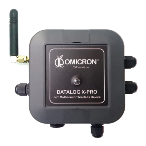
Section 2: Overview The internet of things ( IoT) multisensor wireless device D atalog X-PRO is designed for remote monitoring of multiple processes requiring high safety and measurement precision. In support of your automation needs, it is fitted to receive up to 3 sensors of multiple types (listed in Section 5). The system is delivered with a rechargeable Li-Ion Battery, necessary means to attach the Main Unit enclosure to where is recommended, its AC/DC adapter, and all purchased wireless communication modules. -
Page 9: Datalog X-Pro Insight: Parts
2.2 Datalog X-PRO Insight: Parts Figure 2-1 Overview of uncovered Datalog X-PRO 1. Main board (P/N X-PRO1.0 BOARD): T he base board takes care of the multiple detected sensors and delivers data to the communications module. This part includes main supply and battery terminals;... - Page 10 3. Sensor interfaces (for part numbers, refer to Appendix C or to Datalog X-PRO Datasheet): These terminals allow binding of external sensors, chosen by the user. Specifications and requirements for the sensors that these interfaces receive are listed below. Every interface has an in-built light indicator to mark whether a sensor is properly operating or not.
-
Page 11: Section 3: Mounting Guidelines
Section 3: Mounting Guidelines To properly mount the system, please consider the instructions and suggestions given in the following chapters. Plan all wiring before installing D atalog X-PRO . Also consider the cabinet space, hardware dimensions and rated environmental conditions. Use good wiring practices to minimize problems that may occur due to electrical interference. -
Page 12: Dimensions
3.2 Dimensions 3.2.1 Main Unit Enclosure The Main Unit enclosure is a standard network ASA squared plastic box. Its dimensions are indicated by the following schemes: Figure 3-1 Main Enclosure elements Datalog X-PRO enclosure elements Top cover Bottom base Blind lids Gasket www.omicroning.co March 2020... -
Page 13: Antenna
Figure 3-2 Main Enclosure Dimensions Dimensions in mm. Dark Grey enclosures made from ABS UL94-V0 plastic for high flammability rating. 3.2.2 Antenna The system uses an external helical antenna to reinforce the transmissions of its telecommunications module. This peripheral component requires the most amount of clear space. Its dimensions are shown in the following diagram: Figure 3-3 Antenna Dimensions 3.2.3 Protective Valve... -
Page 14: Mounting Indications
● The protective valve has IP68 protection rating (can be submerged in water 2m/60min) and -40°C ~ 125°C operating temperature range. Figure 3-4 Protective Valve 3.3 Mounting Indications 3.3.1 Main Unit To secure Main Unit enclosure to a wall: 1. Find the mounting holes covered by the blind lids at opposite borders of the Main Unit enclosure. - Page 15 Figure 3-5 Reference example of similar device mounted in a pole NOTE: Remember that, since Datalog X-PRO operates with sensors and accessories attached, it is recommended to leave enough space around the Main Unit to let it hold comfortably its peripherals;...
-
Page 16: Section 4: Electrical Installation Foreword
Section 4: Electrical Installation Foreword Consider implementing safeguards independent to D atalog X-PRO when designing the wiring and grounding plans for your application. This helps to assure optimum system operation, provides additional electrical noise protection for your application and the D atalog X-PRO... -
Page 17: Electrical Ratings
4.2 Electrical Ratings Main Unit Ratings (X-PRO1.0 BOARD): • R ated main input voltage: 6 to 24VDC. • M ax. Electric Current: 0.5A. • O vervoltage Category: Battery Ratings (P/N UBBP01): • R ated Voltage: 3.7VDC. •... -
Page 18: Indoor Use: Connection With Power Adapter (Supplied)
through its cable gland for supply cables; so the user can use this cable to connect a 6 to 24 V DC power supply or an appropriate Solar Panel (not supplied). Alternatively, and only for indoor use, the user can connect the device to a 12V DC power adapter (supplied). Follow the next directives for the different options. - Page 19 The following image illustrates how to connect the referred protection and disconnection elements to the Datalog X-PRO and the solar panel: Figure 4-2 Scheme of Installation of the Datalog X-PRO with a Solar Panel Remember that positive DC disconnect switch terminal should be connected to Datalog X-PRO´s red power cable, and that negative DC disconnect switch terminal should be connected to Datalog X-PRO´s black power cable end.
- Page 20 To avoid the overheating of Datalog X-Pro caused by solar radiation directly over it, it is recommended to install the device vertically and at the shadow of the solar panel (See figure 4-2). Make sure that the IP67 protection of the the Solar Panel or the Datalog X-PRO does not get affected or impaired by the mounting.
-
Page 21: Section 5: Sensors Selector Guide
Section 5: Sensors Selector Guide Exceeding the ranges defined for any sensors Interface could cause damage or unpredictable operation, which could result in death or severe personal injury and/or property damage. To avoid any risk, Datalog X-PRO manufacturer could be reached to receive further assistance on how to properly connect peripherals. - Page 22 Purpose Related Sensors ➔ Temperature and humidity ➔ Pressure ➔ Flow ➔ Analog Signals: 4-20 mA /0-10 V Measurement of industrial Signals: Industrial Applications for different types of sensors and transmitters. ➔ Digital Modbus RTU signals. ➔ CO, CO2, O2, 4-20mA transmitters.
-
Page 23: Sensors Connection To Datalog X-Pro
5.2 Sensors Connection to Datalog X-PRO NOTE: ● Datalog X-PRO is delivered with its ordered sensors connected. ● For correct connection to one external sensor, refer to Appendix C. ● To replace or install a new ordered sensor, follow the guidelines in Appendix B. In accordance to customer orders, ... - Page 24 Figure 5-2 Cutted Sensor Wires. Next, unscrew the cap of the cable gland from the external terminal box to allow the sensor cable to enter it. Insert the ends of the sensor into the external terminal Box. Depending on the thickness of the cable, select the correct rubber bushing of 5 mm or 7.4 mm, both are supplied.
-
Page 25: Section 6: Configuration
Section 6: Configuration 6.1 Normal Operating Mode and Alternative Device States The Datalog X-PRO is delivered in Sleep/off State, to wake it for the first time, join the magnet provided one time near the main unit top cover (See Figure 6-1) ; after this, the system will automatically enter Normal Operating Mode... -
Page 26: Alternative Device States
Figure 6-1 Appropriate position to locate outer magnet near Datalog X-PRO. 6.2 Alternative Device States While in Normal Operating Mode, as long as a magnet is placed near the Main Unit, as described before, the LED Indicator will shine red. Depending on the number of times the magnet is briefly brought close to the Main Unit, users can reach one of the alternative states indicated below: www.omicroning.co... -
Page 27: Service Mode
Figure 6-2 Alternative Device Operating States 6.2.1 Service Mode Datalog X-PRO must be configured to specify necessary resources to allow the appropriate wireless transmission of data, besides particularities related to each sensor to be used. Service Mode allows this setting. T his mode can be accessed after briefly joining a magnet near the main unit 4 times. -
Page 28: Send Data
In Service Mode, the in-built Wi-Fi® module generates a local Wi-Fi® network (whose SSID is the prefix “ I oTDevice _ ”, followed by Main Unit’s factory ID; for example, “ I oTDevice_bcddc212345 ” ), to which any device suited for internet navigation (such as a smartphone, or a PC) can connect. ... -
Page 29: Change Sigfox Zone
6.2.4 Change Sigfox Zone Datalog X-PRO 1.0 is able to transmit in zones 2 or 4 of Sigfox network. Therefore, if the user wants to configure the zone in which the device operates, he should b riefly join a magnet near the Main Unit 10 times.... - Page 30 Figure 6-4 Wi-Fi® Configuration page 2. In the form at the bottom of the Configure Wi-Fi® page, e nter the credentials (SSID and password) of the network to which you want Datalog X-PRO to connect; then press Save. If the entered credentials are invalid, the next page will appear: Figure 6-5 Not Proper Wi-Fi®...
-
Page 31: Connect Datalog X-Pro To Sigfox® Wireless Networks
Figure 6-6 Proper Wi-Fi® Configuration 6.4 Connect Datalog X-PRO to Sigfox® Wireless Networks By default Datalog X-PRO is automatically connected to Sigfox® networks to transmit data, if it counts with the required module; so the user does not need to do special configuration to make use of this technology. - Page 32 Figure 6-7 Other Information page www.omicroning.co March 2020...
-
Page 33: Section 7: Centriomega® Remote Control And Monitoring Platform
Section 7: Centriomega® Remote Control and Monitoring Platform Datalog X-PRO, work in conjunction with Remote Monitoring WEB platform Users can access Remote Monitoring Platform via WEB, to perform, among other things: ● Remote monitoring and visualization of historical data records, in graphs and data tables, from up to 2 years. -
Page 34: Reviewing Historical Data
7.2 Reviewing Historical Data Dashboards are interfaces where relevant data is presented to the users. The referred platform allows to edit or create custom Dashboards to integrate any information desired (if using an account with permission to do so); however, by default it offers panels for remote monitoring of the data published by all devices linked to the platform, and panels to display Alarms or Events that have recently occurred. -
Page 35: Reviewing Devices, Their Variables, And Configuration
Figure 7-3 Dashboard visualization Example To learn how to modify said elements and how to configure a Dashboard, refer to the recommended manufacturer's guide. 7.3 Reviewing Devices, their Variables, and Configuration A Device is a virtual representation of a physical device that takes data from sensors and transmits them through a particular network to the platform. - Page 36 Figure 7-4 Device Selection Page After selecting a particular Device, the user is able to see the information that corresponds to such Device in multiple panels and Variables. Reviewing the Variables of a certain Device allows checking the update status and presence of each Variable.
-
Page 37: Reviewing Alarms And Programmed Events
To review the historical data of a certain Variable, in a Device, select a Variable to access to its historical data. Figure 7-6 Variable Historical Data 7.4 Reviewing Alarms and Programmed Events Events (or Incidents) are configurable conditions that activate the sending of alert messages via email, SMS, Telegram or Webhooks. - Page 38 Figure 7-6 Events Configuration To review the last activity of an Event (its log of updates, or the times in which one of its conditions have been violated), the user can press the Log icon associated to any Event to see a table like the following: Figure 7-7 Events Historical www.omicroning.co...
- Page 39 To review the Dashboard with the recently activated Alarms, refer to section 7.2, and look for the Dashboard whose name contains the suffix -Alarms. This Dashboard will contain a table like the following: Figure 7-7 Events Dashboard To learn how to modify the configuration of an Event, refer to the manufacturer's guide, provided for it.
-
Page 40: Appendix A: Specifications And Reference Data
Appendix A: Specifications and Reference Data A.1 Specifications A.1.1 Performance specifications Recommended Environmental conditions: ● Altitude: up to 2600 m. ● Ambient Temperature: 41°F – 104°F (5°C to 40 °C). ● Maximum Relative Humidity: 100% Recommended environmental conditions: Temperature 77 °F ±9 °F (25 °C ±5 °C) Relative humidity 25 - 75% Reference accuracy Refer to Appendix C. -
Page 41: Power Supply
Measurement principle and range Refer to Appendix C. Sensor Connection Guide to find specifications of different sensors for Datalog X-PRO. A.1.3 Power supply Supply voltage 6 – 24 V DC Max. 0.5 A Power consumption Max. 6 W @ 12 V DC ... - Page 42 A.1.4.2 Wi-Fi Module Radio M odule: ESP12F AiThinker WiFi Module, 2.4 GHz. FCC ID: 2ADUIESP-12 www.omicroning.co March 2020...
-
Page 43: Appendix B: Installation Procedure For A New Sensor
Appendix B: Installation Procedure for a New Sensor Exceeding the ranges defined for any Interface channel could cause damage or unpredictable operation, which could result in death or severe personal injury and/or property damage. To avoid any risk, Datalog X-PRO manufacturer should be reached to receive further assistance on how to properly connect peripherals. - Page 44 As mentioned above, D atalog X-PRO user can connect up to three different sensors, if their type is one of those supplied by the manufacturer. To do this, Main Unit must be uncovered, and the steps indicated below should be followed: 1.
- Page 45 3. On the base board, locate the appropriate Interface to connect the sensor. Next, unscrew the nearest cable glands cap to said Interface, to allow sensors ends to enter into the Main Unit. 4. Before introducing the sensor terminals to the Main Unit through the cable gland, bear in mind that the loosen cap must be inserted in the sensor cable as follows: Figure B-4 Installation of the Cable 5.
- Page 46 Figure B-6 Sensor Cables Connection 7. After all the steps above are completed, the connected sensor should look like this: Figure B-7 Sensor connected to Datalog X-PRO. Figure B-8 Interface Pin-Out. In the scheme: ● VCC_S: should be connected to sensor’s VCC. 3.3V. ...
- Page 47 ● A1_IN: T his pin should be used as an analog input channel; It can be used to measure directly currents from 4 to 20mA, or voltages from 0 to 10V DC (for voltage measurement, a 450 ohm in series resistor should be connected). ●...
-
Page 48: Appendix C: Sensor Connection Guide
Appendix C: Sensor Connection Guide C.1 Analog 4 to 20 mA Sensor Interface P/N ANA-420mA 4-20mA signal is a common output for many industrial transmitters, for variables such as: temperature, flow, pressure, distance, humidity, voltage, current and more. The Datalog X-PRO 4 to 20 mA interface converts this analog signal to digital and sends it to the Internet for subsequent analysis. - Page 49 C.1.3 Connection Diagram Figure C1-1 4-20mA Sensor Interface Connection Figure C1-2 External Sensor Connection through Terminal Box www.omicroning.co March 2020...
-
Page 50: Analog 0-10 V Sensor Interface P/N Ana-010V
C.2 Analog 0-10 V Sensor Interface P/N ANA-010V 0-10V DC or 0-5V DC signals are common outputs for many industrial transmitters, that measures variables such as: temperature, flow, pressure, distance, humidity, voltage, current and more. The Datalog X-PRO 0 to- 10V interface converts this analog signal to digital and sends it to the Internet for subsequent analysis. - Page 51 This Action or improper connection exceeding the ranges defined for the Interface channel could cause damage or unpredictable operation, which could result in death or severe personal injury, and/or property damage. To avoid any risk, Datalog X-PRO manufacturer should be reached to receive further assistance on how to properly connect peripherals.
-
Page 52: Digital Binary (Dry-Contact, Switches) Sensor Interface P/N Dig_Diy1
C.3 Digital Binary (dry-contact, switches) Sensor Interface P/N DIG_DIY1 The Digital binary 1/0 is a common industrial signal that indicates ON/OFF states of machines, motors, valves, open/close doors, and more. The D atalog X-PRO Digital Two Inputs Binary Interface (DIG-DY1) easily takes digital states, counts the quantity of events, and can be programmed to send an alert when a detected state changes. - Page 53 DO NOT CONNECT ANY VOLTAGE OR CURRENT SOURCE TO A DIGITAL INTERFACE DIG-DIY01. ONLY CONNECT A DRY CONTACT OR A SWITCH Exceeding the ranges defined for any Interface channel could cause damage or unpredictable operation, which could result in death or severe personal injury and/or property damage.
-
Page 54: Digital Rs-485 Modbus Interface P/N Dig_Mod485
C.4 Digital RS-485 Modbus Interface P/N DIG_MOD485 The Digital Modbus communication protocol is an industrial common protocol supported by many different devices like PLCs, Speed Motor Controls, Power Meters, Chillers and more. The D atalog X-PRO Digital RS-485 Modbus Interface (DIG-MOD485) can be programmed to read Modbus signals and send them to the Internet for subsequent analysis. - Page 55 DO NOT CONNECT ANY VOLTAGE OR CURRENT SOURCE TO A DIGITAL INTERFACE DIG-MODB485. ONLY CONNECT MODBUS SIGNALS Exceeding the ranges defined for any Interface channel could cause damage or unpredictable operation, which could result in death or severe personal injury and/or property damage.
-
Page 56: Digital I2C Sensor Interface
C.5 Digital I2C Sensor Interface The I2C Digital interface provides complete integration, which gives the user serial communications with different implemented sensors with I2C technology, which has become the standard for simple communications inside equipment, machinery and sensors. The D atalog X-PRO Digital I2C interface acquires this digital signals and sends them to the Internet for subsequent analysis. - Page 57 C.5.4 Digital I2C Sensors P/N available Sensor Picture DIG-TH1 Digital Temperature and Humidity sensor Resolution: 0.1°C / 0.1% R.H. Accuracy: 0.5°C / 3% R.H. Range: 0 to 80°C 0 to100% R.H. DIG-THP1 Digital Temperature, Humidity and Atmospheric pressure sensor Resolution: 0.1°C / 0.1% R.H.
-
Page 58: Digital Temperature Sensor (1-Wire) P/N Dig-Temp1
C.6 Digital Temperature Sensor (1-Wire) P/N DIG-TEMP1 The Digital Temperature interface provides complete integration with the DS18B20 Temperature Sensor I.C. manufactured by Dallas Sensor. The D atalog X-PRO Digital 1-Wire interface acquires sensor digital signal and sends it to the Internet for subsequent analysis. C.6.1 D.C. - Page 59 Exceeding the ranges defined for any Interface channel could cause damage or unpredictable operation, which could result in death or severe personal injury and/or property damage. To avoid any risk, Datalog X-PRO manufacturer should be reached to receive further assistance on how to properly connect peripherals. Remember that Contact Information is provided at the beginning of this document.
- Page 60 www.omicroning.co March 2020...
- Page 61 Phone: +1 (786) 584-7439 Latin America Regional Office Omicron Ingenieria SAS Address: Cra 46 # 38 -62 Off 502 Medellin - Colombia Phone: +57 (4) 2328381 WhatsApp +57 (317)4365062 comercial @omicroning.co www.omicroning.co © 2018 Omicron Ingenieria SAS. All rights reserved. www.omicroning.co March 2020...
Need help?
Do you have a question about the DATALOG X-PRO 1.0 and is the answer not in the manual?
Questions and answers