Advertisement
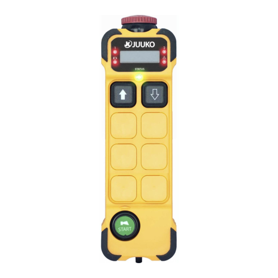
Transmitter
SHORT
LED Signal
Failure Analysis
LONG
-
Corrosion on the battery
LED red
LED green
terminals.
-
Low battery.
-
Damage batteries.
-
Transmitter is not
LED red
LED green
communicating with the
receiver.
-
Push button damaged.
LED red
LED green
-RF error
LED red
LED green
Receiver
Should an error occur, the LED of the receiver will indicate the cause.
SHORT
LED Signal
Failure Analysis
LONG
-RF error
LED red
LED green
-
Receiver is not powered.
LED green
LED red
The receiver is receiving data.
LED red
LED green
Chapter 4: Troubleshooting
Solution
-Clean the battery terminals
.
-
Replace the batteries.
-
Check the power supply
of the receiver.
-
Check the fuse in the
receiver
-
Contact the dealers.
-Check the antenna and
make sure it is not loose.
-Change a new RF module.
-Contact dealer
Solution
-Check the antenna and
make sure it is not loose.
-Change a new RF module.
-Contact dealer
-
Check the fuse.
-Check the power supply.
12
Radio remote control system
BASIC INSTALLATION INSTRUCTIONS
【C2/C2E/C2Q/C2EQ】
K200
K808
K400
K1000
K600
K1200
K800
(English)
Standard settings
(K200~K808)12C&20C-EN01
Advertisement
Table of Contents

Related Manuals for Juuko C2

Summary of Contents for Juuko C2
-
Page 1: Chapter 4: Troubleshooting
Radio remote control system Transmitter BASIC INSTALLATION INSTRUCTIONS SHORT LED Signal Failure Analysis Solution LONG Corrosion on the battery -Clean the battery terminals 【C2/C2E/C2Q/C2EQ】 LED red LED green Replace the batteries. terminals. K200 K808 Low battery. Damage batteries. K400 K1000... -
Page 2: Chapter 3: Receiver
3.Safety Feature. Both the Transmitter and the Receiver will “time out” after 30 minutes of inactivity. This can be altered, ask your dealer. Guarantee, service, repairs and maintenance JUUKO products are covered by a guarantee/warranty against material, construction and manufacturing faults. During the guarantee/warranty period,... -
Page 3: Chapter 3: Wiring Diagram
Chapter 3: Wiring Diagram Chapter 1: CUSTOMER INFORMATION Thank you for purchasing a JUUKO product. K808 READ ALL INSTRUCTIONS CAREFULLY BEFORE MOUNTING, INSTALLING AND CONFIGURATING THE PRODUCT. SOUTH This manual includes general information concerning the operation of the radio remote control transmitter. - Page 4 Chapter 2:General description Chapter 3: Wiring Diagram The K series (C2/C2E/C2Q/C2EQ) transmitter comes in di erent versions, featuring K600 2, 4, 6, or 8 pushbuttons. The transmitter also features 2-step pushbuttons. Both SOUTH steps of each pushbutton can operate di erent functions like controlling the speed of a movement, step 1: slow, step 2: fast.
-
Page 5: Chapter 2: General Description
Chapter 3: Wiring Diagram Chapter 2: General description Technical data K200 Black TRANSMITTER Brown Frequency range 434.040Mhz~434.790Mhz Modulation method 4 FSK Typical operating range 100M Power enable (DC-) Control system Orange Antenna impedance E.STOP Yellow Typical response time for Stop 50mS~100mS command and commands Master Output... -
Page 6: Instruction Guide
Chapter 3: Receiver Chapter 3: Receiver Instruction guide Receiver WARNING! DO NOT FLUSH MOUNT THE RECEIVING ASSEMBLY. WARNING! The receiver must NOT be opened by any other than a quali ed installer. PLEASE MAINTAIN PROPER CLEARANCEAS SHOWN. PLEASE USE Make sure to turn the electricity o before opening the receiver. THE SUPPLIED MOUNT! Area must be free RF module...
Need help?
Do you have a question about the C2 and is the answer not in the manual?
Questions and answers