Table of Contents
Advertisement
Quick Links
Service Manual
This service information is designed for experienced repair technicians only and is not designed for use by the general public.
It does not contain warnings or cautions to advise non-technical individuals of potential dangers in attempting to service a product.
Products powered by electricity should be serviced or repaired only by experienced professional technicians. Any attempt to service or
repair the products dealt with in this service information by anyone else could result in serious injury or death.
In order to avoid frosting, be assured of no refrigerant leakage during the installation or repairing of refrigerant circuit.
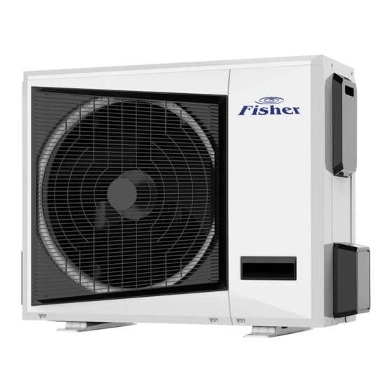
Air-to-Water Heat pump
WARNING
PRECAUTION OF LOW TEMPERATURE
Advertisement
Table of Contents

Related Manuals for Fisher FHOF-WHS-100CE3

Summary of Contents for Fisher FHOF-WHS-100CE3
- Page 1 Service Manual Air-to-Water Heat pump WARNING This service information is designed for experienced repair technicians only and is not designed for use by the general public. It does not contain warnings or cautions to advise non-technical individuals of potential dangers in attempting to service a product. ...
-
Page 3: Table Of Contents
1. General Information ............................6 1.1 Measurements ............................6 1.2 External outlook ............................6 1.3 Nomenclature ............................7 2. Specifications ..............................8 2.1 FHOF-WHS-100CE3 , FHOF-WHS-160CE3-3F ..............8 2.2 FHIF-WHS-120CE3, FHIF-WHS-160CE3 ....................12 3. Features ................................. 13 3.1 Outdoor unit ............................13 3.2 Hydronic module ............................. - Page 4 R32 ATW Service Manual 11.3 Refrigerant pipe work ..........................37 11.4 Water piping ............................41 11.5 Electrical wiring ............................ 47 11.6 Field wiring ............................49 12. Start-up and configuration ........................... 55 12.1 DIP switch settings ..........................55 12.2 Pre-operation checks ..........................56 12.3 Water pump ............................
-
Page 5: Safety Precautions
R32 ATW Service Manual Safety Precautions Read the following “SAFETY PRECAUTIONS” carefully before installation. Electrical work must be installed by a licensed electrician. Be sure to use the correct rating and main circuit for the model to be installed. ... - Page 6 R32 ATW Service Manual 10. Do not insert your fingers or other objects into the unit, high speed rotating fan may cause injury. 11. Do not sit or step on the unit, you may fall down accidentally. 12. For electrical work, follow local wiring standard, regulation and this installation instruction. An independent circuit and single outlet must be used.
- Page 7 R32 ATW Service Manual electrical contact between equipment and building is allowed. Insulator must be installed in between. 30. Any work carried out on the Indoor Unit / Outdoor Unit after removing any panels which is secured by screws, must be carried out under the supervision of authorized dealer and licensed installation contractor.
-
Page 8: General Information
R32 ATW Service Manual 1. General Information 1.1 Measurements 1.1.1 Outdoor units Model Dimension (W*H*D) Net/Gross Weight (kg) Power Supply FHOF-WHS-100CE3 56.3/61 1032× 810× 445 220~240V/1Ph/50Hz FHOF-WHS- -160CE3-3F 1014× 1430× 450 124/138 380~415V/3Ph/50Hz 1.1.2 Hydronic module Model Dimension (W*H*D) Net/Gross Weight (kg) Power Supply 490×... -
Page 9: Nomenclature
R32 ATW Service Manual 1.2.2 Hydronic module FHIF-WHS-120CE3 FHIF-WHS-160CE3... -
Page 10: Specifications
R32 ATW Service Manual 2. Specifications FHOF-WHS-100CE3 Model Power supply V/Ph/Hz 220~240/1/50 Performance data Capacity 10.8 Heating Power input 2.82 (A7° C/W35°C) kW/kW 3.84 Capacity Heating Power input (A7° C/W55°C) kW/kW 2.74 Capacity 10.6 Heating Power input (A2° C/W35°C) kW/kW 3.53... - Page 11 R32 ATW Service Manual Tube pitch(a)× row 25× 21.7 pitch(b) Φ9.52 inner grooved Tube dia. and type copper Fin space Air side heat exchanger Hydrophilic Fin type (code) aluminum Coil 1003× 750× 43.3 length× height× width Number of circuits Piping connections Type Flaring Liquid pipe...
- Page 12 R32 ATW Service Manual FHOF-WHS-160CE3-3F Model V/Ph/Hz 380~415/3/50 Power supply Performance data 17.28 Capacity Heating 4.75 Power input (A7° C/W35°C) 3.64 kW/kW 15.36 Capacity Heating 5.91 Power input (A7° C/W55°C) kW/kW 16.96 Capacity Heating 5.06 Power input (A2° C/W35°C) 3.35 kW/kW 14.72 Capacity...
- Page 13 R32 ATW Service Manual Tube pitch(a)× row 25×21.7 pitch(b) Φ9.52 inner grooved Tube dia. and type copper Fin space Air side heat Hydrophilic exchanger Fin type (code) aluminum Coil 995×1350×43.3 length× height× width Number of circuits Piping connections Flaring Type Liquid pipe Φ9.52 Dia.(OD)
- Page 14 R32 ATW Service Manual Hydronic module Hydronic box FHIF-WHS-120CE3 FHIF-WHS-160CE3 V/Ph/ Power supply 220~240/1/50 220~240/1/50 ℃ Leaving Space heating 25~60 25~60 ℃ water Space cooling 5~25 5~25 temperatur ℃ Domestic hot water 40~60 40~60 Max. power input Max. current input Sound power level dB(A) Dimension (W×...
-
Page 15: Features
R32 ATW Service Manual 3. Features 3.1 Outdoor unit Compact structure design, flexible installation. Long piping up to 30 meter with height difference 20 meter, no need extra refrigerant within 5m refrigerant pipe length. Heating, cooling & domestic hot water mode, total heat solution. Pic.3-1 Total heat solution ... -
Page 16: Hydronic Module
R32 ATW Service Manual Pic.3-3 Water outlet temperature range DC inverter technology to guarantee optimal operational reliability and efficiency. Offers heating capacity of 85% at -15°C thanks to the large heat exchanger and large compressor. Seasonal space heating energy efficiency is up to A++ @35℃ and @55℃. 3.2 Hydronic module ... -
Page 17: Operation Range
R32 ATW Service Manual 4. Operation range Pic.4-1 Heating mode operation range Pic.4-2 Cooling mode operation range... - Page 18 R32 ATW Service Manual Pic.4-3 Domestic hot water mode operation range...
-
Page 19: Fhif-Whs-120Ce3 Fhif-Whs-160Ce3
Rear side Front side Microphone 1.2 m (body height +1 )/2 m Pic.5-1 Outdoor unit sound test diagram Model Sound pressure level (dB(A)) FHOF-WHS-100CE3 FHOF-WHS-160CE3-3F Hydronic module: Pic.5-2 Hydronic module sound test diagram Model Sound pressure level (dB(A)) FHIF-WHS-120CE3 FHIF-WHS-160CE3... -
Page 20: Accessories
R32 ATW Service Manual 6. Accessories Accessories for hydronic module Name Pic. Notes Wired controller communication 25m 5-core communication wire wire Y-type filter Connected in water inlet pipe Wall mounted board 5kΩ, for DHW tank Temperature sensor Cable ties Wired controller cover Outdoor unit installation... -
Page 21: Performance Data
R32 ATW Service Manual 7. Performance data 7.1 Heating capacity / FHOF-WHS-100CE3 FHIF-WHS-120CE3 Tamb 2.86 2.25 1.27 5.43 3.12 1.74 5.40 3.39 1.59 5.04 3.55 1.42 4.70 3.51 1.34 -25/- 7.28 3.01 2.41 7.20 3.19 2.26 6.08 3.02 2.01 5.64 3.09... - Page 22 R32 ATW Service Manual / FHOF-WHS-160CE3-3F FHIF-WHS-160CE3 Tamb 8.96 5.26 1.70 8.64 5.71 1.51 8.48 5.98 1.42 8.00 5.93 1.35 4.84 3.87 1.25 -25/- 12.00 5.08 2.36 11.52 5.38 2.14 10.24 5.09 2.01 9.60 5.22 1.84 8.96 5.97 1.50 6.57 4.94 1.33 -20/-...
-
Page 23: System Diagram
R32 ATW Service Manual 8. System diagram... -
Page 24: Wiring Diagram
R32 ATW Service Manual 9. Wiring diagram 9.1 Outdoor unit 9.1.1 FHOF-WHS-100CE3 9.1.2 FHOF-WHS-160CE3-3F... - Page 25 R32 ATW Service Manual CN37...
-
Page 26: Hydronic Module
R32 ATW Service Manual 9.2 Hydronic module 5 6 7 L1 N1 Reserved... -
Page 27: Printed Circuit Board
R32 ATW Service Manual 9.3 Printed circuit board 1. Single phase outdoor unit Main integrated PCB Display board 2. 3-phase outdoor unit... - Page 28 R32 ATW Service Manual Main PCB 3. Hydronic module Main PCB...
- Page 29 R32 ATW Service Manual Filter board...
-
Page 30: Exploded View
R32 ATW Service Manual 10. Exploded view 10.1 Outdoor unit FHOF-WHS-100CE3 18 19 Part name Part name Front panel EXV assy 12.1 EXV body Middle partition part 12.2 EXV coil Fan motor support assy Chassis assy Fan motor Right front panel... - Page 31 R32 ATW Service Manual FHOF-WHS-160CE3-3F Part name Part name Stand column 13.1 4-way valve Fan motor support assy 13.2 4-way valve coil DC fan motor EC part Fan blade 14.1 Current transformer Front panel 14.2 Main PCB 14.3 Transformer Condenser part 14.4 Filter board Middle partition part...
-
Page 32: Hydronic Module
R32 ATW Service Manual 10.2 Hydronic module Part name Part name Bottom plate assy Heat exchanger water outlet pipe assy Water pan foam 1 Middle beam Water pan foam 2 EC box cover Water pan assy EC box Expansion tank support 21.1 Transformer Foam 1... -
Page 33: Installation
1 meter away from televisions and radios. This is to prevent image interference and noise in those electrical appliances. (Noise may be generated depending on the conditions under which the electric wave is generated, even if 1 meter is kept.) 11.1.2 Installation dimension for outdoor unit Model FHOF-WHS-100CE3... - Page 34 R32 ATW Service Manual Model FHOF-WHS-160CE3-3F...
- Page 35 R32 ATW Service Manual Single unit installation More than one unit installation Unit: mm...
-
Page 36: Installation For Hydronic Module
R32 ATW Service Manual 11.2 Installation for hydronic module 11.2.1 Select the best location There should not be any heat source or steam near the unit. A place where air circulation in the room is good. A place where drainage can be easily done. ... - Page 37 R32 ATW Service Manual (3) Outline dimensions and installation dimension. (mm) 11.2.3 Install the hydronic module (1) Fix wall mounted panel Choose a wall or support that is fully reliable and safe to withstand twice the weight of the unit. ...
- Page 38 R32 ATW Service Manual mounting hole diameter is 8.5 mm) In order to ensure the reliability of the load-bearing, the wall drilling hole needs to reach a depth of 45~50 mm. (2) Engage the hooks on the indoor unit to the slots of installation plate. Ensure the hooks are properly seated on the installation plate by moving it left and right.
-
Page 39: Refrigerant Pipe Work
R32 ATW Service Manual 11.3 Refrigerant pipe work 11.3.1 Refrigerant piping Decide piping length and then cut by using pipe cutter. Remove burrs from cut edge. Make flare after inserting the flare nut (locate at valve) onto the copper pipe. Align center of piping to valves and then tighten with torque wrench to the specified torque as stated in the table. - Page 40 R32 ATW Service Manual Attention In order to prevent oxidation inside the copper tube during copper pipe welding, nitrogen filling must be taken. Otherwise the scale will block the refrigeration system! 11.3.2 Connection between outdoor unit and hydronic module Note: The refrigerant circuit of the hydraulic module contains a small amount of Nitrogen, which is used to keep the pressure and detect leakage.
- Page 41 R32 ATW Service Manual Note: Oil return elbow radius R≤100mm, 10 oil return elbows must be located per 5m as shown above; when the height difference between indoor and outdoor unit exceeds five meters, oil reserve elbow and backstop elbow should be set according to the relative position of outdoor unit and indoor unit.
- Page 42 R32 ATW Service Manual after completion. 3) The outdoor unit cannot be connected when holding pressure. 11.3.7 Vacuum pumping 1) A vacuum pump with a vacuum degree of -0.1μm or less and gas displacement of above 40L/min shall be used. 2) The outdoor unit does not need to be vacuumed.
-
Page 43: Water Piping
R32 ATW Service Manual 11.3.10 Pipe insulation treatment 1) Insulate the gas side and liquid side pipes separately. 2) Use closed-cell insulation material, with B1 flame retardant rating and 120'Chigh temperature resistance. 3) The outer diameter of the copper tube is φ9.52, the thickness of the insulation cotton is not less than 15 mm;... - Page 44 R32 ATW Service Manual Water pipe connection Water outlet pipe DN32 Water inlet pipe DN32 11.4.1 Water quality The water quality shall meet the values specified in the following table. Otherwise, the scaling will appear in the heat exchanger and the floor heating system after a period of use, which will affect the heat exchange efficiency and cause failure.
- Page 45 R32 ATW Service Manual a. Turn off the power; b. Close the water inlet of the water tank; c. Open the water tank outlet and drain valve; 4) Follow the steps below to drain the water from the hydronic module. a.
- Page 46 R32 ATW Service Manual HEATING MODE COOLING MODE...
- Page 47 R32 ATW Service Manual HEATING MODE WITHOUT COOLING MODE DHW MODE WITHOUT COOLING MODE...
- Page 48 R32 ATW Service Manual HEATING MODE WITHOUT DHW MODE AND DHW TANK ONLY DHW MODE...
-
Page 49: Electrical Wiring
R32 ATW Service Manual 11.5 Electrical wiring Please select a dedicated power supply for indoor unit and outdoor unit respectively. The power supply has specified branch circuit with leakage protector and manual switch. Outdoor unit and indoor unit connect with required power supply which is 220-240V~ 50Hz or 380-415V 3N~ 50Hz. - Page 50 R32 ATW Service Manual Wiring and control Electrical connection for single-phase and three-phase units Attention When using the 2-core shielded cable as the signal cable, connect the shielded mesh to "E" of the terminal block. When using the 3-core shielded cable as the signal cable, the shielded mesh must be grounded.
-
Page 51: Field Wiring
R32 ATW Service Manual 11.6 Field wiring Outdoor unit Hydronic module Wired controller Contactor for circulation water pump (filed supply) Contactor for booster heater Buffer tank (filed supply) (filed supply) DHW tank (filed supply) T7 temperature sensor Booster heater filed supply) Electric 3-way valve (filed supply) Circulation water pump (filed supply) Electric 2-way valve (filed supply) - Page 52 R32 ATW Service Manual Room thermostat cable Electric 2-way valve control cable Electric 3way valve control cable Temperature sensor cable Power supply cable for circulation water pump Power supply cable for booster heater Power supply cable for circulation water pump Power supply cable for booster heater Communication wire between ODU and hydronic module Equipment must be grounded.
- Page 53 R32 ATW Service Manual When the unit is in cooling mode, SV3 has no output. When the unit is in heating mode, defrosting mode and anti-freezing mode, SV3 has a 220V AC output. Please use a normal closing valve for this unit. 3.
- Page 54 R32 ATW Service Manual When hydronic module SW2-2 is in ON position, the unit is controlled by room thermostat. And the unit can’t run DHW mode. When “H” signal is connected, the unit will run heating mode, and the default setting temperature is 50℃.
- Page 55 R32 ATW Service Manual Connection of the booster heater cable depends on the application. Only when the domestic hot water tank is installed will this wiring be needed. The unit only sends ON or OFF signal to the booster heater. An additional contactor is needed and a dedicated terminal is needed to supply power to the booster heater.
- Page 56 R32 ATW Service Manual When the unit has error code, alarm port has a 220V output.
-
Page 57: Start-Up And Configuration
The unit should be configured by the installer to match the installation environment (outdoor climate, installed options, etc.) and user expertise. 12.1 DIP switch settings 1. Single phase outdoor unit Reserved Reserved FHOF-WHS-100CE3 Capacity setting Reserved Reserved …… …… 2. 3-phase outdoor unit... -
Page 58: Pre-Operation Checks
R32 ATW Service Manual 12.2 Pre-operation checks After the installation of the unit, check the followings before powering on the units: Field wiring: Make sure that the field wiring between the switch box and unit and valves (when applicable), unit and room thermostat (when applicable), unit and domestic hot water tank, and unit and backup heater box have been connected according to the instructions, according to the wiring diagrams and to local laws and regulations. - Page 59 R32 ATW Service Manual...
-
Page 60: Operation And Control
R32 ATW Service Manual 13. Operation and control This wired controller is used for communicating with the system main board, controlling the operating status of the system through touch keys, and displaying the working status of the whole system through its LCD screen. -
Page 61: Setting The Clock
R32 ATW Service Manual Timer Timer Indoor Temp. Cooling Heating mode mode mode Time / temp. Reserved The wired controller and the main board will check whether the communication is successful within 1 minute after power-on. If the communication is not successful, the main control board (30 seconds) and the wired controller will alarm the communication fault. -
Page 62: Running Mode And Temperature Setting
R32 ATW Service Manual 13.3 Running mode and temperature setting 13.3.1 Running mode setting Short press MODE button to select running mode. 1. When the unit is without DHW mode Heating only model: the wired controller can only select heating mode. ... -
Page 63: Display Shows
R32 ATW Service Manual When the unit is set combination mode and the unit is running one mode a) In main interface, short press , to enter current running mode temperature setting interface, one digital tube flashes. (no operation for 5 seconds to exit setting) b) Press button to choose the target temperature. -
Page 64: Electric Auxiliary Heating
R32 ATW Service Manual 13.5 Electric auxiliary heating 1. When the unit is in heating mode or timer heating mode is ON, in the main interface, press electric auxiliary heating button , the hydronic module electric heater icon is displayed to open electric heater. - Page 65 R32 ATW Service Manual weekly timer setting interface. 1. After entering the weekly timer setting mode, icon flashes, press button to select , and press button, when icon is always on, enter the start time setting. 2. Days setting: Long press button to switch setting items.
-
Page 66: Power-Down Memory Setting
R32 ATW Service Manual otherwise, the weekly timer setting will fail. 2. Long press button, it will come back to last setting interface. 13.8.2 Weekly timer setting query Press setting button twice, the weekly timer icon flashes, short press button to enter the weekly timer setting interface. -
Page 67: Error Code Display
R32 ATW Service Manual When hydronic module is without Ambient temperature T4 DHW function, it will show 0. Capacity of hydronic module Capacity (HP) = value * 0.1 Operating capacity demand of hydronic module Capacity (HP) = value * 0.1 Water pump gear 13.11 Error code display When the unit has error, the icon... -
Page 68: Troubleshooting
R32 ATW Service Manual 14. Troubleshooting Before starting the troubleshooting procedure, carry out a thorough visual inspection of the unit and look for obvious defects such as loose connections or defective wiring. 14.1 Spot check 14.1.1 Spot check in outdoor unit For single phase outdoor unit, press up button to enter spot check. - Page 69 R32 ATW Service Manual Primary current Secondary current Primary voltage Secondary voltage Last failure or protection code No protection or fault display --- Control parameter For dev elopers only Control parameter For dev elopers only End of check 14.1.2 Spot check in hydronic module Press SW4 check button to enter spot check.
-
Page 70: Error Code And Troubleshooting
R32 ATW Service Manual Press query button to enter spot check. Press up and down button to turn pages. Display content Remarks AC side setting water temperature Ts1 When hydronic module is without Domestic hot water setting temperature Ts2 DHW function, it will show 0. Water inlet temperature of heat exchanger Tw_in Water outlet temperature of heat exchanger Tw_out Water outlet temperature of hydronic module T1... - Page 71 R32 ATW Service Manual 2. Communication wire sequence is not right. Reconnect the wire in the right sequence. 3. Whether there is a high magnetic field or high power interfere, such as lifts, large power transformers, etc. To add a barrier to protect the unit or to move the unit to the other place.
- Page 72 R32 ATW Service Manual install the EXV coil in the right location DHW mode: Water tank heat exchanger is smaller than the required 1.7m2 (10-16kW unit) or 1.4m2 (5-7kW unit) Cooling mode: 1. Heat exchanger cover is not removed. Remove it. 2.
- Page 73 R32 ATW Service Manual 5. Over charge the refrigerant volume. Recharge the refrigerant in right volume. 6. Water flow rate is low, there is air in system, or pump head is not enough. Release the air and reselect the pump. 7.
- Page 74 R32 ATW Service Manual interfere, such as lifts, large power transformers, etc. To add a barrier to protect the unit or to move the unit to the other place. T1 fault of water outlet temperature 1. The T1 sensor connector is loosening. Reconnect it. sensor 2.
- Page 75 R32 ATW Service Manual 6. Check that the pump speed setting is on the highest speed. 7. Make sure that the expansion tank is not broken. 8. Check that the resistance in the water circuit is not too high for the pump Protection for insufficient water flow T1 and Tw_out simultaneous fault The same to E2 and E8.
Need help?
Do you have a question about the FHOF-WHS-100CE3 and is the answer not in the manual?
Questions and answers