Advertisement
Quick Links
Quick Start Guide
QNET Mechatronic Interfacing
Step 1: Check Components and Details
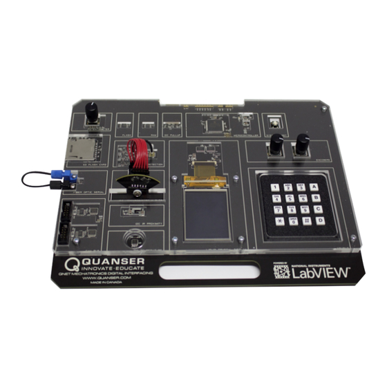
The Quanser QNET Mechatronic Interfacing consists of a single PCB module (shown in Figure ??)
Note: The QNET curriculum resources are available for
download at www.ni.com/ni-elvis/courseware or www.quansershare.com/qnets
Step 2: Additional Components Required for Setup
To complete your QNET Mechatronic Interfacing setup, you will
also need the following hardware:
1. NI ELVIS II or ELVIS II+ workstation
2. +5VDC / 5A, +15VDC / 2A, -15VDC / 0.8A Power Supply
3. USB Cable
QNET MI Quick Start Guide
for
Figure 1: QNET Mechatronics Interfacing Board
LabVIEW™
(b) Power Supply
Figure 2: ELVIS II
(a) ELVIS II
(c) USB Cable
(+)
Components
v 1.0
Advertisement

Summary of Contents for National Instruments Quanser QNET MI
- Page 1 Quick Start Guide QNET Mechatronic Interfacing LabVIEW™ Step 1: Check Components and Details Figure 1: QNET Mechatronics Interfacing Board The Quanser QNET Mechatronic Interfacing consists of a single PCB module (shown in Figure ??) Note: The QNET curriculum resources are available for download at www.ni.com/ni-elvis/courseware or www.quansershare.com/qnets Step 2: Additional Components Required for Setup To complete your QNET Mechatronic Interfacing setup, you will...
-
Page 2: Step 4: Setup Hardware
Step 3: Install LabVIEW and Add-Ons Make sure the following versions of LabVIEW™ and required add-ons are installed: LabVIEW™ 2013 or later 2. NI-DAQmx 9.8 or later 3. NI ELVISmx 4.5 or later Step 4: Setup Hardware To setup the QNET Mechatronics Interfacing, please read the following instructions carefully. For full details, see the QNET Mechatronic Interfacing User Manual. - Page 3 Connect the power supply to the back of the NI ELVIS Connect the USB cable to the back of the NI ELVIS Power on the NI ELVIS II using the power switch on the rear of the workstation. The READY and ACTIVE LEDs should briefly light, fol- lowed by the READY LED alone.
- Page 4 Ensure that the "+5V Power" LED on the should light up. QNET board is lit. The LCD screen should display the Quanser and National Instruments logos. If the LCD shows a blank screen or another image, please contact Quanser's technical support team.
- Page 5 Step 5: Testing the QNET MI Open the Quick Start folder from the Mechatronics Interfacing folder in the QNET Resources. QNET sources available download Make sure your PC, NI ELVIS II , and from www.ni.com/ni-elvis/courseware QNET module are powered ON www.quansershare.com/qnets Open the LabVIEW VI (*.vi) found under the Quick Start...
- Page 6 The graph displays the output intensity of the tri-color LED, calculated from the position of the accelerometer, potentiometer, and the left- hand encoder. Adjusting the position of any of these sensors should cause the associated value to change both on the graph and in the light output of the LED.
- Page 7 Step 6: Troubleshooting Please review the following before contacting Quanser's technical support team. The +5V Power LED A. Ensure that the PCI connector on the QNET module is properly connected to the on the QNET module female connector on the NI ELVIS II unit.
Need help?
Do you have a question about the Quanser QNET MI and is the answer not in the manual?
Questions and answers