Table of Contents
Advertisement
Quick Links
Advertisement
Chapters
Table of Contents

Summary of Contents for LS Industrial Systems GIPAM
- Page 1 User Manual GIPAM•GIMAC - II•GMPC - III...
- Page 2 GIPAM User Manual GIPAM USER MANUAL (Digital Integrated Protection & Monitoring Equipment)
-
Page 3: Table Of Contents
GIPAM User Manual CONTENTS 1. Summary ………………………………………………………………………… 3 2. Characteristics …………………………………………………………………. 3 3. Main Features …………………………………………………………………… 4 4. External view and System structure 4.1 External view and part name ……………………………………………………………… 5 4.2 System structure …………………………………………………………………………….. 5 5. Capacities 5.1 Measuring Part ………………………………………………………………………………. 6 5.2 Protection Part ………………………………………………………………………………. -
Page 4: Characteristics
16bit μ-processor. 2) Self Diagnosis Function GIPAM detects an error of CPU operation or circuit of signal input immediately and it indicates caution and reason of error. It also has a data transmission function . 3) An outstanding flexibility GIPAM corresponds suitably to a change of PT ratio, CT ratio and wirings through setting DIP Switches. -
Page 5: Main Features
● Error message is indicated on front DOT Matrix LED when error occurs. 4) Communication Function - All data and information can be transferred to a host computer up to 255 sets of GIPAM with high speed (250kbps) through internal communication module. -
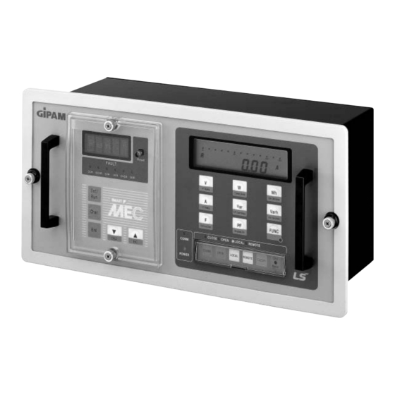
Page 6: External View And System Structure
GIPAM User Manual 4 External view and System structure 4-1 External view and part name 4-2 System structure... - Page 7 GIPAM User Manual 5 Spacification 5-1 Metering 1)Input specification Contents Rating Wiring Type 1P2W, 1P3W, 3P3W, 3P4W Input Frequency 60Hz Range Voltage AC10~132V/AC20~264V Current 0.2~6A 2) Range of the metering result Meter Menu Metering Value Displayed Range Accuracy(%) Remarks Voltage(V)
- Page 8 Power (Red) LED lamp will be on during the system is operated. Comm (Red) LED lamp blinks when GIPAM is communicated with host. Func (Red) When operator select special function mode, LED lamp will be turned on. 5) Setting a metering part...
- Page 9 GIPAM User Manual 6) Other specification Contents Voltage Under 0.1 VA Input burden Under 1 VA Current Voltage DC110[V] (93.5~121V)] Control Power Current Under 15[W] Data Backup Over 10 years by adopting NV-RAM. Operation -10~55℃ Temperature Storage -25~75℃ Humidity 80% RH(Non-condensing) Insulated Resistance Over DC500V 10MΩ, Tested part is the same as impulse voltage.
-
Page 10: Measuring Part
GIPAM User Manual 6 Operating 6-1 Measuring Part 6-1-1 Calibration Mode A calibration mode of metering consists of 2 modes. One is adjusting offset and gain of A/D converter and the other is selecting the ratings of analog input signal. (Please do not adjust a calibration mode temporarily. If there are necessity of adjustment, refer to appendix.) - Page 11 GIPAM User Manual 2) Voltage Each phase of voltage measurement value will be displayed continuously with the “V” unit by repeating to push the touch switch “V”. Type of wiring Displayed phase Remark 1P2W Measurement value of each phase 1P3W RN →...
- Page 12 GIPAM User Manual 4) FUNC+W: It displays a settled own address at telecommunication part of main board. 5) FUNC+Var: It displays the number of operation time of the circuit breaker which is connected to CB ON input contact. 6) FUNC+PF: It displays all the measured data by the following sequence in a row(V →...
-
Page 13: Protection Part
GIPAM User Manual 6-1-6. Display for the system error Error code will be displayed in case of it is out of order. Error code is displayed as followings : Error 0: PT ratio setting is wrong. Error 1: CT ratio setting is wrong. - Page 14 2) Protection function setting Dot Matrix LED displays [Run…] as normal state when control power is supplied to GIPAM. Press [Set/Run] key to move to setting mode to set following protection functions. Note 1> D2, D4, D8 : Definite time delay (t = 2, 4, 8) 2>...
- Page 15 GIPAM User Manual OVR operated Ov (value) (Value of Indicator x 110(V) x PT Ratio → Operated voltage of OVR. UVR operated Uv (value) (Value of Indicator) x 110(V) x PT Ratio → Operated Voltage of UVR. OVGR operated (value) (Value of Indicator) x 190(V) x GPT Ratio →...
- Page 16 GIPAM User Manual...
- Page 17 GIPAM User Manual...
- Page 18 GIPAM User Manual...
- Page 19 GIPAM User Manual...
- Page 20 GIPAM User Manual...
- Page 21 GIPAM User Manual...
- Page 22 GIPAM User Manual 6-2-3. The formula of Time Characteristic Curve 1) Time Characteristic t = T x TL (sec) ⓐ "T" is an operating characteristic and it should be one of the following formulas.(Time Delay Characteristic, IEC 255-3 is applied) 0.14...
- Page 23 GIPAM User Manual 2) The value of operating characteristic * The operating time below is the value when TD equals 1. ⓐ Standard Inverse Time ⓑ Very Inverse Time (I/Is) (sec) (I/Is) (sec) 1.00 ---> 1.00 ---> 2.00 ---> 10.029 2.00...
- Page 24 GIPAM User Manual 6-2-4. Characteristic Operation Curve 1) SI(Standard Inverse Time)- OCR, OCGR, OVGR 0.14 × TL (TL : 0.05 ~ 1.00) 0.02 ( I / Is )
- Page 25 GIPAM User Manual 2) VI(Very Inverse Time)- OCR, OCGR 13.5 × TL (TL : 0.05 ~ 1.00) ( I / Is ) - 1...
- Page 26 GIPAM User Manual 3) EI(Extremely Inverse Time)- OCR, OCGR × TL (TL : 0.05 ~ 1.00) ( I / Is )
- Page 27 GIPAM User Manual 4) LI(Long Inverse Time)- OCR, OCGR × TL (TL : 0.05 ~ 1.00) ( I / Is ) - 1...
- Page 28 GIPAM User Manual 5) SGR - Current and voltage in Zone 1 : Vo > Vos, Io > Ios - RCA : Relay Characteristic Angle...
- Page 29 GIPAM User Manual 7. Installing & Operating Device 7-1. How to install 1) Set CT/PT Ratio, Wiring and select relays with DIP Switches located on the Main Board of the device. 2) Set an Address Number with the Address Knob which is deeply inside of the Main Board.
- Page 30 GIPAM User Manual The DIP Switches are set as follows. 1) CT Ratio CODE (Table 1) 2) PT Ratio CODE (Table 2) Setting Bits Setting Bits DIP S/W #1 DIP S/W #1 5 : 5A 110 : 110V 10 : 5A...
- Page 31 GIPAM User Manual 7-3. Setting a Communication Address Number It is set by the two knobs on top of the Main Board and each knobs has hexa-decimal scale marks from ‘0’ to ‘F'. Using these two knobs, it is possible to set 255 Address Numbers from '01' up to ‘FF'. For...
- Page 32 GIPAM User Manual 2) Sigle-Phase Three-Wire System 3) Three-Phase Three-Wire System (with 2-CTs)
- Page 33 GIPAM User Manual 4) Three-Phase Three-Wire System (with 3-CTs) * with 3PTs...
- Page 34 GIPAM User Manual 5) Three-Phase Four-Wire Syste (note.1) 6) Connecting with ZCT 7) Connecting with GPT...
- Page 35 GIPAM User Manual 7-6. External connection 1) Avoid parallel connection with other devices that generate noises. 2) Press the CLEAR Switch to initialize all data after installing device. Warnings! It must be supplied the well-smooting DC power whose ripple rate is under 6%...
- Page 36 GIPAM User Manual 3) Terminal Block 7-7. External Dimension(mm)
- Page 37 GIPAM User Manual 8. Communication 8-1. Communication Specific. Serial communication with high speed and reliability using the custom LSI ASIC designed by LGIS. 1) Transmision Speed : 250kbps 2) Cable Lenth : max. 1000m 3) Insulation : Pulse Transformer 4) Connection : 4-wire Multi-drop...
- Page 38 1) Event Recording ・when the relays in GIPAM has been operated (OCR, OCGR, OVR, UVR, SGR, OVGR) ・when the CB has been controlled ・when the status of the CB has been changed 2) Synchronization ・Function of synchroinsing among the devices through the communication network.
-
Page 39: Measuring Part
GIPAM User Manual ② GIPAM <---> GIPAM Terminal Resistor --------- 120Ω GIPAM #1 GIPAM #2 GIPAM #3 9 Maintenance 9-1. Troubleshooting Condition Cause Proper Step - The supplied power is under - Trace to the cause of If all the indicators on... - Page 40 - An input value of the present current is displayed on LCD after all the indicators are on for a little while(0.5~0.6sec) - "RUN .. " is displayd on DOT-Matrix LED of the protection part. 10. Ordering Information GIPAM - 115 N Standard SOE Function...
- Page 41 GIPAM User Manual [ Appendix ] 1. TIME CHART 1-1. Time Table for Standard Inverse(SI) 0.10 0.20 0.30 0.40 0.50 0.60 0.70 0.80 0.90 1.00 200% 1.003 2.006 3.009 4.012 5.015 6.017 7.020 8.023 9.026 10.029 300% 0.630 1.260 1.891 2.521...
- Page 42 GIPAM User Manual 0.10 0.20 0.30 0.40 0.50 0.60 0.70 0.80 0.90 1.00 1000% 0.150 0.300 0.450 0.600 0.750 0.900 1.050 1.200 1.350 1.500 1100% 0.135 0.270 0.405 0.540 0.675 0.810 0.945 1.080 1.215 1.350 1200% 0.123 0.245 0.368 0.491 0.614...
- Page 43 GIPAM User Manual 1-4. Time Table for Long Inverse(LI) 0.10 0.20 0.30 0.40 0.50 0.60 0.70 0.80 0.90 1.00 200% 12.000 24.000 36.000 48.000 60.000 72.000 84.000 96.000 108.000 120.000 300% 6.000 12.000 18.000 24.000 30.000 36.000 42.000 48.000 54.000 60.000...
- Page 44 GIMAC-II User Manual GIMAC-II USER MANUAL (Digital Integrated Metering & Control Equipment)
-
Page 45: Installation And Operation
GIMAC-II User Manual CONTENTS Presentation Features & system diagram 2-1 Features 2-2 System Diagram Specification 3-1 Metering Operational functions 4-1 Display 4-2 Special function switch 4-3 Etc. Installation and operation 5-1 Set the CT/PT ratio. 5-2 Wiring Odering Information... - Page 46 1 Presentation GIMAC-II is multi-functional measuring & control equipment adopt and intensify the electronic technology to the High voltage and medium voltage switchgear. 1) Compact and multi functional measuring equipment . Measure the following electronic data only by the GIMAC-II. 3phase voltage, 3phase current, Watt, Var, Watt hour, Var hour, power factor, frequency 2) Intensify the circuit breaker control circuit to one body.
-
Page 47: Specification
2-2 System Diagram CB-ON CB-OFF Severe fault Digital Slight fault Output Local Main Remote OCGR Digital OVGR Input CB-ON CB-OFF Communi- cation Power Input Communication Port Control Module DC110V Power 3 Specification 3-1 Metering 1) Input Item Rating Connection 1P2W, 1P3W, 3P3W, 3P4W Frequency 60Hz Input... - Page 48 3) Setting * PT Ratio : DIP switch (#1) 4BIT * CT Ratio : DIP switch(#2) 5BIT * CLEAR Reset : Watt hour, CB on time, CB operation, Average power factor Data reset PT ratio Connetion Fault CT ratio Calibration Barrery on(Back-up) [ DIP switch #1] [DIP switch #2]...
-
Page 49: Operational Functions
4 Operational functions 4-1 Display GIMAC-II display the measuring the data by pressing the button in the lower part of the front surface of the GIMAC-II first and then selecting the data you want. 1) Voltage . 1phase 2wire : displays the data by Voltage unit. . -
Page 50: Special Function Switch
4-2 Special function switch Enter the special function mode by pressing the ‘Func switch’. If you press the ‘Func switch’ again the standard mode comes. In the special function mode the followed measuring switches display the new data as described below. 1) V switch: Display the PT ratio setting value of the dip switch in the back plate. - Page 51 Input contact 1 Input contact 2 Display LED 1 Display LED 2 Fault output Reset 5 Installation and operation 1) Set the followings ①CT/PT ratio by use of the DIP switch in the rear part of the equipment. ②Mis-operation display mode ③Wiring connection type ④Communication address (optional) ) 2) Apply the control power...
-
Page 52: Set The Ct/Pt Ratio
5-1 Set the CT/PT ratio. According to the CT/PT ratio, you can set the Dip switch by referring the following table. The WH/VARH Pulse output is decided by the ratio of the CT/PT ratio. Bit setting Bit setting Dip S/W #1 Dip S/W #2 110 : 110V 0 5 : 5A... -
Page 53: Wiring
5-2 Wiring... - Page 54 1) 3P4W (3-CT) 2) 3P3W (3CT) * With 3PTs...
- Page 55 3) 3P3W (2CT) 4) 1P3W...
-
Page 56: Odering Information
5) 1P2W 6 Odering Information... - Page 57 GMPC-III User Manual GMPC-III USER MANUAL (Protocol converter-III)
- Page 58 10.2 Data Transmission (GIMAC II ·················································································· 10.3 Control Command I ················································································································· 10.4 Control Command II················································································································ 11 GIPAM Protocol·························································································31 11.1 Data communication of GIPAM, SOE GIPAM ········································································ 11.2 Control Command ················································································································ 11.3 Command for controlling CB on/off ························································································ 12 Modbus ······································································································49 12.1 Setting of MODBUS...
-
Page 59: Components
1 Components LG»Œ »Œ GMPC-III Main Body (1EA) I-NET CABLE (1EA) RS232C CABLE (1EA) POWER CALBE (1EA) 485 Connector T/M Connector... -
Page 60: Overview
2 Overview 2.1 General View 2.2 Front Face View ① Display Window - Displaying time and setting menu ② SYNC LED - Being on-and-off while a synchronizing data is transmitting. ③ Time Master LED - Turned on when Time Master is selected in the setting menu ④... -
Page 61: Rear View
⑥ RUN LED - Turned on when there is a data flow on I-Net port ⑦ IDLE LED - Turned on when there is not any data flow on I-net port ⑧ Error LED - Turned on when any error is on the internal system ⑨... -
Page 62: General Description
I-Net standard (Exclusive communication method or standard of LGIS) such as GIMAC or GIPAM and the devices using any other communication standard or protocols. GMPC has RS-232, RS-422 and RS-485 port for it and enables I-Net data to... -
Page 63: System Configuration
4.1 Network Diagram To be connected When using S.O.E function (For synchronization) RS-232C GMPC#2 GMPC#4 GMPC#1 GMPC#3 Multi-serial communication Board I-NET 통신망 GIMAC-III GIPAM DPR #1 DPR #1 GIMAC-II GIMAC-III GIMAC-III DPR #2 GIPAM GIMAC-III DPR #3 DPR #3 GIMAC-II GIMAC-III U-RTU... -
Page 64: Functions
5 Functions 5.1 Interfacing with Central control & monitoring system. GMPC has RS-232 and RS-485 port which applies asynchronous mode for interfacing with Central control & monitoring system. It is capable to set all parameters about transmission such as transmission speed for RS-232 and RS-485 port. Because there is a control signal for modem, it is possible to use external modem via RS-232 port. -
Page 65: Settings
5.4 Displays and Settings 5.4.1 GMPC is able to display the items in the table as below. Displayed Parameters Details Status of the Device Normal or Error Code The Present Time Year/Month/Day/Min./Sec. Selecting a TIME MASTER Selecting / Remove SYNC. BROADCAST Selecting / Remove I-NET ADDRESS 0x00 ~ 0xFF... - Page 66 5.4.2 It is capable to set the following items in the table via the front panel of the GMPC. Setting Parameters Setting Range The Present Time Year/Month/Day/Min./Sec. Selecting a TIME MASTER Selecting / Remove SYNC BROADCAST Selecting / Remove I-NET ADDRESS 0x00 ~ 0XFF Choosing a PROTOCOL MODBUS / GMPC(I-NET)
-
Page 67: Data
6 Expression Of Time Data 6.1 Expressing Data of the timer built-in. 6.1.1 Time SYNC. Frame for Time synchronization on I-Net Network. A time information is displayed 32bits-time data in the form of 0[h] 0[m]0.000[s] and it is reset once a day. The form of Sync. -
Page 68: Installation
8 Installation 8.1 The first installation 8.1.1 Connecting to the power. GMPC has two different type which means the RACK Type and the UNIT type and both of them are supplied AC110-220V(Free Voltage) as a control power. The power cable has to be connected to the plug at the rear of the device. The rated voltage and current of the fuse which is inside of the Fuse Holder on the rear of the Unit Type should be checked if it is 220V and 2A. - Page 69 8.1.3 The Connection of I-Net cable GMPC also has communication ports for I-Net communicating with GIMAC and GIPAM and for wiring, it is necessary to be used Multi-drop network configuration with 4 wires as below. TX-1 RX-1 TX-0 RX-0 UNIT Type...
-
Page 70: The First Settings
8.2 The first settings 8.2.1 SELF TEST When GMPC is supplied the power, it carries out a self test within 2 or 3 seconds and changed into ERROR DISPLAY Mode. If there is not any errors on the device, it turns over into TIME DISPLAY Mode. 8.2.2 ERROR DISPLAY It can be only displayed one of the Error Codes on the front window when an error is on the device. - Page 71 8.2.4 YEAR / MONTH / DAY DISPLAY The Front window displays the present year/month/day. Pressing the [SEL]key once, it is changed from Display Mode to Setting Mode and the value on the display window goes on and off. To increase this value press [SEL]key.
- Page 72 To store the status selected between On and Off, press the [ENT]key. If you press the [MENU] key while changing the values on the setting menu, all the values that has been changed are canceled and it is changed into Display Mode. To move to the next menu on Display Mode, press the [MENU]key.
- Page 73 Pressing the [SEL]key once, it is changed from Display Mode to Setting Mode and the value on the display window goes on and off. And each time pressing the [SEL] key, it displays RS-232 or RS-485 on the window one by one. To store the one selected between RS-232 and RS-485, press the [ENT]key.
-
Page 74: Menu Tree
MENU TREE Time Date Time Master Protocol Sync. I-NET Address RS-232/RS-485 Parity Bit Baud rate... -
Page 75: Protocols
9.1 Introduction GMPC transfers the data from Central Control & Monitoring system(PC/MODEM) to subordinate devices such as GIMAC/GIPAM if there is a response from them or vise versa. And a structure of the data which is communicated between Central Control &... -
Page 76: Transmitting Junction Protocol
[P1] + [P2] + [DEST] + [0:00:LEN] + [DATA-0] + … + [DATA-n] + [ECC] - It is used for transmitting data from the Host system (PC/MODEM) to GIMAC/GIPAM or vise versa. And FN in the data frame for transmission is 00 at this point. - Page 77 The data frame that GMPC has received is discarded when there is ECC error on it . The data frame that GMPC has received is recognized as abnormal response (E bit = 1) when there is an error in value on it. There are two different types of synchronization which are ROUGH SYNC and PRECISION SYNC.
- Page 78 9.4.2 PRECISION SYNC GMPC-III Host System START_PRECI_SYNC REQUEST_ADJUST TIME_ADJUST END_PRECI_SYNC The Host system transmits START_PRECI_SYNC frame to GMPC. And The Host system stores the time when the first frame and the first bit is started transmitting (A1) at this point. GMPC stores the point that the first frame and the first bit of START_PRECI_SYNC frame is received (B1).
- Page 79 If there is an error on the data that GMPC received, GMPC requests restarting SYNC SEQUENCE via transmitting REQUEST_RESTART_SYNC frame to the Host system. Since the Host system receives REQUEST_RESTART_SYNC frame from GMPC, it restarts SYNC SEQUENCE as requested. If there is an error on the data that the Host system received, the Host system restarts SYNC SEQUENCE via transmitting SYNC_PRECI_SYNC frame to GMPC.
-
Page 80: Internal Setting
9.5 Internal Setting PROTOCOL [P1] + [P2] + [DEST] + [E:10:LEN] + [DATA-0] + … + [DATA-n] + [ECC] It is used for monitoring status of GMPC or changing the setting information. And FN in the data frame for transmission is 10 at this point. The data in [DEST] is disregarded. - Page 81 [DATA-0] 0x01 Read_Status [DATA-1] year The value of year that GMPC displays at present [DATA-2] The value of month that GMPC displays at present [DATA-3] The value of day that GMPC displays at present [DATA-4] hour The value of hour that GMPC displays at present [DATA-5] The value of minute that GMPC displays at present [DATA-6]...
- Page 82 PC ← GMPC-III 0xFF + 0x00 + 0x?? + 0X42 + 0x02 + ON/OFF + ECC [DATA-0] 0x02 WRITE_TIME_MASTER [DATA-0] 0x00 0X01 9.5.3 WRITE_SYNC_ENABLE PC → GMPC-III 0xFF + 0x00 + 0x?? + 0X42 + 0x03 + ON/OFF + ECC [DATA-0] 0X03 WRITE_SYNC_ENABLE...
-
Page 83: Gimac-Ii Protocol
10 GIMAC-II Protocol 10.1 Data Request (PC → GIMAC II) COMMAND Description Details Requesting Status data Status of Input/Output points Requesting Phase Current data IR,IS,IT Requesting Line Voltage data VRS,VST,VTR Requesting PF, W, Var data PF,W,VAR Requesting F, Wh, Varh data FREQ,WH,VARH Requesting Phase Voltage data (3P4W) VRN,VSN,VTN... - Page 84 (MSB) 0 0 0 1 0 1 1 1 (LSB) BIT7,6,5 : Null : CB ON Output : CB OFF Output : 0 = LOCAL , 1= REMOTE : CB ON Input : CB OFF Input f) 6 . byte : 0F ⇒ Status of RESET (MSB) 0 0 0 0 1 1 1 1 (LSB) BIT7~4 : Null...
-
Page 85: Control Command I
Ex.) < CProgram > char RxBuffer[16]; float IR,IS, IT; for(I=0;I<4;I++){ ((char *)(&IR))[I] = RxBuffer[I+1]; ((char *)(&IS))[I] = RxBuffer[I+5]; ((char *)(&IT))[I] = RxBuffer[I+9]; 10.3 Control Command I COMMAND(1BYTE) +SUBCOMMAND(1BYTE)+CHECKSUM(1BYTE) * COMMAND : 0x20 ** SUBCOMMAND : See the table below. *** CHECKSUM = (COMMAND+ SUBCOMMAND) % 0x100 SUB COMMAND Description WH/VARH RESET... - Page 86 Control CODE1 Control CODE2 Description Selecting CB ON Selecting CB OFF Cancel Selecting CB Control 10.4.2 Command of operating Control point COMMMAND(1BYTE) + SUBCOMMAND(1BYTE)+ Control CODE1(1 BYTE) + Control CODE2(1 BYTE) + CHECK SUM(1BYTE) * COMMAND : 0x2d ** SUBCOMMAND : 0x55 *** Control CODE1, Control CODE2 : See the table below ****CHECKSUM=(COMMAND + SUBCOMMAND + Control CODE1 + Control CODE2) % 0x100...
-
Page 87: Gipam Protocol
11.1 Data communication of GIPAM, SOE GIPAM Device ID is GIPAM (GIPAM-115N : 82), SOE GIPAM (GIPAM-115S : 83) GIPAM-115N does not respond to requesting data which is related to SOE function or responds “ NAK Message” . 11.1.1 Status Data of GIPAM, SOE GIPAM... - Page 88 - Ir>> : Instantaneous Characteristic of OCR (R Phase) > : Time Delay Characteristic of OVGR >> : Instantaneous Characteristic of OVGR. - Sys. : Internal Error of GIPAM - SOE = 1(ON) : Data exists in SOE Buffer at present. 11.1.2 CURRENT...
- Page 89 - Line Voltage Data Command MSB (Byte 3) Byte 2 Voltage between R and S phase (1P3W : Between R and N Phase) Byte 1 LSB (Byte 0) MSB (Byte 3) Byte 2 Voltage between S and T phase (1P3W : Between S and N Phase) Byte 1 LSB (Byte 0) MSB (Byte 3)
- Page 90 MSB (Byte 3) Byte 2 Volt-Ampere Reactive Byte 1 LSB (Byte 0) Data Check Sum Check Sum - The representation follows IEEE Standards (4 Byte Floating Point Number) - (Reactive Power) = SQRT{(Apparent Power) – (Active power) - Checksum(1Byte) = (Command 1Byte + Data 12Byte) / 256 ⇒ The residual ※...
- Page 91 11.1.6 Phase Voltage - Requesting Phase Voltage Information Command Sub Command - Phase Voltage Data Command MSB (Byte 3) Byte 2 R Phase Voltage (R-N) Byte 1 LSB (Byte 0) MSB (Byte 3) Byte 2 S Phase Voltage (S-N) Byte 1 LSB (Byte 0) MSB (Byte 3) Byte 2...
- Page 92 - Checksum(1Byte) = (Command 1Byte + Data 8Byte) / 256 ⇒ The residual ※ Checksum is the sum of each bytes not to include OVERFLOW. 11.1.8 SOE Data GIPAM-115N does not respond to requesting data which is related to SOE function or responds “ NAK Message” . - Requesting SOE Data...
- Page 93 Device ID Fault occurred Time 4 Byte msec Time Status Information 1 ~ 4 Byte Data Check Sum Check Sum - Checksum = (Command 1Byte + Sub Command 1Byte + Device ID 1byte + Fault occurred t time 4Byte + Data 1~4Byte) / 256 ⇒ The residual ※...
- Page 94 ※ Checksum is the sum of each bytes not to include OVERFLOW. c) Information of setting Relays Command Sub Command Device ID T-Valid Fault occurred Time Remote Local Relay Setting Remote Local Fault Reset Fault Reset Data Check Sum Check Sum - Checksum(1 Byte) = (Command(1Byte) + Sub Command(1Byte) + Device ID(1Byte) + Fault occurred time(4Byte) + Relay Setting(1Byte) / 256 ⇒...
- Page 95 Fault occurred time(4Byte) + Data(4Byte)) / 256 ⇒ The residual ※ Checksum is the sum of each bytes not to include OVERFLOW. 11.1.9 GIPAM Setting Data - Requesting the set Data Command 00h : Measuring Part Setting 01h : OCR/OCGR Setting...
- Page 96 Set Data of Measuring Part Command Sub Command Setting CT Ratio Refer to setting DIP Switch in the GIPAM Manual Setting PT Ratio Refer to setting DIP Switch in the GIPAM Manual Setting System wiring Setting Relay enables Number of CB operation...
- Page 97 - Checksum(1Byte) = (Command(1Byte) + Sub Command(1Byte) + Data(11Byte) / 256 ⇒ The residual ※ Checksum is the sum of each bytes not to include OVERFLOW - Time Characteristic Curve for OCR/OCGR Data T/C Curve Definite 2sec Definite 4sec Definite 8sec Standard Inverse Very Inverse Extremely Inverse...
- Page 98 - Checksum(1Byte) = (Command(1Byte) + Sub Command(1Byte) + Data(11Byte) / 256 ⇒ The residual ※ Checksum is the sum of each bytes not to include OVERFLOW. - Selecting the Relay operation(OVR/UVR) Data Selecting the Relay Operation Disable Alarm Only Alarm & Trip d) OVGR/SGR Setting Data Command Sub Command...
- Page 99 Time error of former synchronous code when received. It indicates time gap between the time in the synchronous code and the one that stored timer inside GIPAM when the last synchronous code is received and it is also described as a 2Byte-signed integer.
-
Page 100: Control Command
The event is set as SOE Event. Sub Command has to be ‘0x00’. 100 : Setting the Remote The protection relay part of GIPAM is set on the remote. Sub Command designates a relay which wills to be set. ACK/NAK Response a) ACK It replies when the control command of which Reply Bit is set executed completely. - Page 101 Command Sub Command Field of the control command executed Sub Command 2 Field of the control command executed Data Check Sum Check Sum b) NAK Command Error Code 01 ~ 04 Data Check Sum Check Sum Error Code 01 : Wrong control command, 02 : Not being able to execute 03 : Lack of Data, 04: DATA range is incorrect 11.2.2 Command for controlling a point...
-
Page 102: Command For Controlling Cb On/Off
GIPAM replies with ACK Signal. Transmitting the command for operating the point selected before time’s up. GIPAM replies with ACK Signal as well as outputs the control signal. 11.3.2 Reacting to other command after receiving the command for selecting control point. - Page 103 11.3.3 Control Command 11.3.3.1 Command selecting control. Bit 7 Bit 6 Bit 5 Bit 4 Bit 3 Bit 2 Bit 1 Bit 0 Command Sub Command selecting Data 1 Data selecting Data 2 Data Check Check Sum Selecting Data Selecting Data 1 Selecting Data 2 –...
- Page 104 Time-out data is displayed in 10ms and the length is 16 bits. Default value of Time-out is 5 seconds. It has to be set over than 1 second. 11.3.4.2 Reading Time-out data (Added to the Data for setting GIPAM) Requiring Timeout Data Command...
-
Page 105: Modbus
12 Modbus 12.1 Setting of MODBUS TOPIC All of the following examples are applied to WONDERWARE MODICON MODBUS I/O SERVER - MAX COIL READ COUNT - MAX COIL WRITE COUNT - MAX REGISTER READ COUNT - MAX REGISTAER WRITECOUNT 12.2 ITEM/POINT NAME 12.2.1 SIGNED REGISTER It has a value of decimal 0 ~ 65535 range when WONDERWARE MODICON MODBUS I/O SERVER is used. -
Page 106: Usable Address Range In Each Device
GMPC III MODBUS communication. For example when GMPC III receives the data which is a type of Floating point as below from other devices such as GIMAC II, GIPAM, and so forth. " 01h 02h 03h 04h "... - Page 107 OP CODE Description DATA TYPE ADDRESS Description 0 – Bit7 : Heavy Fault Output (Previous Status) 8 – Bit7 : Heavy Fault Output (Current Status) 1 – Bit6 : Light Fault Output (Previous 9 – Bit6 : Light Fault Output (Current Status) Status) 2 –...
-
Page 108: Hex82
Example) To send SBO cancel command to GIMAC II with station address number 1 after sending SBO select command QUERY) 01 06 00 00 00 FF C9 8A 12.5.4 GIPAM (When DEVICE ID is Hex82, Hex83) SOE function is excluded when DEVICE ID is Hex82 OP CODE... - Page 109 011 : CB ON counter clear 4 – R-Rst 100 : CB ON time clear 3 - Local 101 : Vo max. clear 110 : all clear 111,xxx : clear nothing GIPAM Internal 33005 Reserved ERROR CODE Current QUERY R Phase Current FLOAT...
- Page 110 OP CODE Meaning DATA TYPE ADDRESS Description Power, Reactive Power FLOAT 33061 Example)33061 F FLOAT 33063 Example)33043 F FLOAT 33065 Example)33045 F Frequency, Active Energy, Reactive Energy Frequency FLOAT 33081 Example)33081 F Active Energy FLOAT 33083 Example)33083 F Reactive Energy FLOAT 33085 Example)33085 F...
- Page 111 OP CODE Meaning DATA TYPE ADDRESS Description 15 - Ir> 7 – OVR 14 – Is> 6 – UVR 13 – It> 5 – VG> 12 – In> 4 – SGR 11 – Ir>> 3 – VG>> 10 – Is>> 2 –...
- Page 112 OP CODE Meaning DATA TYPE ADDRESS Description 7 : local on 3,2 : 0 6 : local off 1 : on Input 5 : remote on 0 : off Input 4 : remote off BIT Operation * LOCAL CLEAR BYTE 33146(H) (Higher 1 BYTE) 7,6 : 1...
- Page 113 OP CODE Meaning DATA TYPE ADDRESS Description Operating Current Value in Instantaneous char. of BCD CODE 33221(L) (Lower 1 BYTE) OCR CURVE BCD CODE 33222 0X (Lower 1BYTE) 0X.XX Operating Time of OCR BCD CODE 33223 Higher BYTE : 0X Lower BYTE : .XX Operating Current Value in Time Delay char.
- Page 114 3 : CB ON counter 6 : fault reset 2 : SOE buffer 5 : Vo max 1 : varh 4 : CB ON time 0 : wh GIPAM Internal TIMER 33284 Calibration DEVICE Name and STRING 33301 Example)33301-33306 M...
- Page 115 DATA TYPE ADDRESS Description VERSION Information SBO ARM TIME Read 33321 Example) To send Query for reading SBO ARM TIME to SOE GIPAM with station address number 1 QUERY : 01 04 0C F8 00 01 B3 6B RELAY FAULT RESET 3041...
- Page 116 Description CB SBO CANCEL 43341 SBO Cancel Command. Example) To send SBO cancel command to SOE GIPAM with station address number 1 after sending SBO select command QUERY) 01 06 0D 0C 00 FF 0B 25 SBO ARM TIMER 43021...
- Page 117 OP CODE Meaning DATA TYPE ADDRESS Description 49803 0 - 31 Hour 49804 0 - 24 49805 0 - 60 49806 0 - 60 Year 39801(H) 00 – 99 39801(L) 0 – 12 39802(H) 0 – 31 Hour 39802(L) 0 - 24 39803(H) 0 - 60 39803(L)
-
Page 118: Intouch And Modbus I/O Server User Manual
13 InTouch and Modbus I/O Server User Manual 13.1 Setting of Modbus I/O Server 13.1.1 Main View of Modbus I/O Server 13.1.2 Com Port Setting - Setting COM port to connect with GMPC III MODBUS ① ② ③ ① Select COM port to connecting with GMPC III MODBUS ②... - Page 119 13.1.3 Topic Definition - Creating New Topic and Modification of setting variables in created Topic ① ② ① Creating new Topic ② Modification of setting variables in created Topic ① ② ③ ④ ⑤ ① Setting the name of Topic.(The name must be the same name of Access Name in Topic Name) ②...
- Page 120 ③ Select Slave ID of Modbus ④ Coil Read : Set maximum number of Coil Registers in a query to 8 Coil Write : Set maximum number of Coil Registers in a command to 8. Register Read : Set maximum number of Registers in a query to 8 Register Write : Set maximum number of Registers in a command to 8.
-
Page 121: Intouch User Manual
13.2 InTouch User Manual 13.2.1 Definition of Tag - Definition of Tag ② ① ③ ④ ⑤ ⑥ ⑦ ⑧ ① Define new Tag ② Select old Tag ③ Type the name of the Tag ④ Select type of the Tag ⑤... - Page 122 13.2.2 Setting Tag Type - A tag with Tag Name starting with “ Memory” is internal tag and a tag with Tag Name starting with “ I/O” is external tag - Discrete : Binary Type, 1bit - Integer : Integer Type, 32bit - Real : Floating Point Type, 32bit - Message : String Type, 131Byte in max 13.2.3 Setting Access Name...
- Page 123 2003-10 Safety Instructions For your safety, please read user’s manual thoroughly before operating. Contact the nearest authorized service facility for examination, repair, or adjustment. Please contact qualified service technician when you need maintenance. Do not disassemble or repair by yourself! Any maintenance and inspection shall be performed by the personnel having expertise concerned.
Need help?
Do you have a question about the GIPAM and is the answer not in the manual?
Questions and answers