
Summary of Contents for Jäger ADwin HSM-24V
- Page 1 ADwin HSM-24V Module for LS Bus Manual ADwin LS Bus, Manual version 1.0, September 2006...
- Page 2 For any questions, please don’t hesitate to contact us: Hotline: +49 6251 96320 Fax: +49 6251 5 68 19 Jäger Computergesteuerte E-Mail: info@ADwin.de Messtechnik GmbH Rheinstraße 2-4 Internet www.ADwin.de D-64653 Lorsch Germany ADwin LS Bus, Manual version 1.0, September 2006...
-
Page 3: Table Of Contents
ADwin Table of Contents Typographical Conventions ..........IV 1 Information about this Manual . -
Page 4: Typographical Conventions
ADwin Typographical Conventions Typographical Conventions "Warning" stands for information, which indicate damages of hardware or soft- ware, test setup or injury to persons caused by incorrect handling. You find "note" next to – information, which have absolutely to be considered in order to guaran- tee an operation without any errors. -
Page 5: Information About This Manual
ADwin Information about this Manual 1 Information about this Manual This manual describes the LS bus and the modules being operated on the LS bus. Additional information are available in – the description of the LS bus interface in the hardware manual for ADwin- light-16, ADwin-Gold or ADwin-Pro. -
Page 6: The Ls Bus
ADwin The LS bus 2 The LS bus The LS bus is a bi-directional serial bus with 5 MHz clock rate. The bus connects an ADwin system via its LS bus interface with up to 15 LS bus modules. Figure shows the standard connections of an LS bus module: Bus input and output with LED, protection earth PE, DIP switch for bus termination and bus address. - Page 7 ADwin The LS bus Module Setting of DIP address switches Module disabled … … Fig. 1 – Module addressing with DIP switches The GND level of the module is connected to the top hat rail, which serves as Protection Earth protection earth (PE).
-
Page 8: Hsm-24V
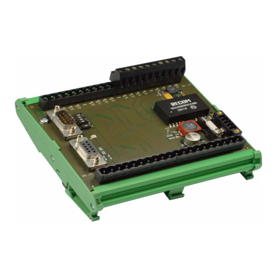
ADwin HSM-24V 3 HSM-24V The LS bus module HSM-24V provides 32 digital channels which process 24V signals. 3.1 Hardware The 32 channels can be set to inputs or outputs in groups of 8. After power-up all channels are set as inputs. The module processes a supply voltage of 19V…... -
Page 9: Software
ADwin HSM-24V SIGNAL GND RESERVED RESERVED RESERVED RESERVED SIGNAL LOW SIGNAL HIGH SIGNAL HIGH SIGNAL LOW RESERVED RESERVED RESERVED RESERVED SIGNAL GND Input LS bus (male) Output LS bus (female) Fig. 3 – Pin assignment LS bus HSM-24V 3.2 Software The functions of the module HSM-24V are easily programmed with ADbasic... - Page 10 ADwin HSM-24V ADwin LS Bus, Manual version 1.0, September 2006...
-
Page 11: Ls Bus
ADwin HSM-24V LS_WATCHDOG_INIT LS_WATCHDOG_ 3.2.1 LS Bus enables or disables the watchdog counter of a specified LS_WATCHDOG_INIT module on the LS bus. If enabled, the counter is set to the start value and is INIT started. Syntax #INCLUDE ADWL16.INC ret_val = LS_WATCHDOG_INIT(ls-module,enable,time) Parameters Specified module address on the LS bus (1…15). - Page 12 ADwin HSM-24V LS_WATCHDOG_INIT Example REM Example prozess for one module HSM-24V and ADwin-L16 #INCLUDE ADWL16.inc init: PROCESSDELAY = 4000000 '10Hz HP PAR_1 = LS_DIO_INIT(1) PAR_2 = LS_DIGPROG(1, 0Fh) 'channels 1…32 as output PAR_3 = LS_WATCHDOG_INIT(1, 1, 1100) 'watchdog time 1.1 sec event: REM set one channel to high, rotating from 1 to 32 INC PAR_10...
- Page 13 ADwin HSM-24V LS_DIO_INIT LS_DIO_INIT initializes the specified module of type HSM-24V on the LS bus LS_DIO_INIT and returns the error status. Syntax #INCLUDE ADWL16.INC ret_val = LS_DIO_INIT(ls-module) Parameters Specified module address on the LS bus (1…15). ls-module LONG Bit pattern representing the error status. ret_val LONG Bit = 0: No error.
- Page 14 ADwin HSM-24V LS_DIO_INIT Example REM Example prozess for one module HSM-24V and ADwin-L16 #INCLUDE ADWL16.inc init: PROCESSDELAY = 4000000 '10Hz HP PAR_1 = LS_DIO_INIT(1) PAR_2 = LS_DIGPROG(1, 0Fh) 'channels 1…32 as output PAR_3 = LS_WATCHDOG_INIT(1, 1, 1100) 'watchdog time 1,1 sec event: REM set one channel to high, rotating from 1 to 32 INC PAR_10...
- Page 15 ADwin HSM-24V LS_DIGPROG LS_DIGPROG sets the digital channels 1…32 of the specified module of type LS_DIGPROG HSM-24V on the LS bus as inputs or outputs in groups of 8. Syntax #INCLUDE ADWL16.INC ret_val = LS_DIGPROG(ls-module, pattern) Parameters Specified module address on the LS bus (1…15). ls-module LONG Bit pattern, setting the channels as inputs or out-...
- Page 16 ADwin HSM-24V LS_DIGPROG Example REM Example prozess for one module HSM-24V and ADwin-L16 #INCLUDE ADWL16.inc init: PROCESSDELAY = 4000000 '10Hz HP PAR_1 = LS_DIO_INIT(1) PAR_2 = LS_DIGPROG(1, 0Fh) 'channels 1…32 as output PAR_3 = LS_WATCHDOG_INIT(1, 1, 1100) 'watchdog time 1,1 sec event: REM set one channel to high, rotating from 1 to 32 INC PAR_10...
- Page 17 ADwin HSM-24V LS_DIG_IO LS_DIG_IO sets all digital outputs of the specified module HSM-24V on the LS LS_DIG_IO bus to the level High oder Low and returns the status of all channels as bit pat- tern. Syntax #INCLUDE ADWL16.INC ret_val = LS_DIG_IO(pattern) Parameters Bit pattern, setting the digital outputs (see table).
- Page 18 ADwin HSM-24V LS_DIG_IO Example REM Example prozess for one module HSM-24V and ADwin-L16 #INCLUDE ADWL16.inc init: PROCESSDELAY = 4000000 '10Hz HP PAR_1 = LS_DIO_INIT(1) PAR_2 = LS_DIGPROG(1, 0Fh) 'channels 1…32 as output PAR_3 = LS_WATCHDOG_INIT(1, 1, 1100) 'watchdog time 1,1 sec event: REM set one channel to high, rotating from 1 to 32 INC PAR_10...
Need help?
Do you have a question about the ADwin HSM-24V and is the answer not in the manual?
Questions and answers