Table of Contents
Advertisement
Available languages
Available languages
Quick Links
Advertisement
Table of Contents

Summary of Contents for Gruppo Ferroli ECOTRONIC tech
- Page 1 ECOTRONIC tech Istruzioni per l'uso e l'installazione Instrucciones de uso e instalación Use and installation instructions Instructions d’utilisation et d’installation Aanwijzingen voor gebruik, installatie en onderhoud...
- Page 2 Bilancio quantità termica (Contabilizzazione) ........................41 Indice de contenido 1. ELEMENTOS DEL REGULADOR ..............................42 Vista frontal ....................................42 Medidas ....................................43 Componentes del kit Ecotronic Tech .............................44 Datos técnicos ..................................44 2. INSTALACIÓN ....................................45 Montaje ....................................45 Asignación de los bornes ..............................46 Primera puesta en marcha ..............................53 3.
-
Page 3: Table Of Contents
Thermal quantity balance (Calculation) ..........................116 Table des matières 1. PANORAMIQUE DU RÉGULATEUR ............................117 Vue de face ..................................117 Dimensions ..................................118 Liste kit Ecotronic Tech ................................ 119 Données techniques ................................119 2. INSTALLATION..................................120 Montage ....................................120 Bornage ....................................121 Première mise en fonction ..............................128 3. - Page 4 ECOTRONIC tech Inhoud 1. OVERZICHT VAN DE REGELAAR ............................154 Vooraanzicht ..................................154 Afmetingen ..................................155 Lijst kit Ecotronic Tech .................................156 Technische Gegevens .................................156 2. INSTALLATIE....................................157 Montage ....................................157 Toewijzing van de klemmen ..............................158 Eerste inbedrijfstelling .................................165 3. SYSTEMEN MET ÉÉN PANEEL ..............................166 Gebruikersinterface ................................166 Werking....................................167...
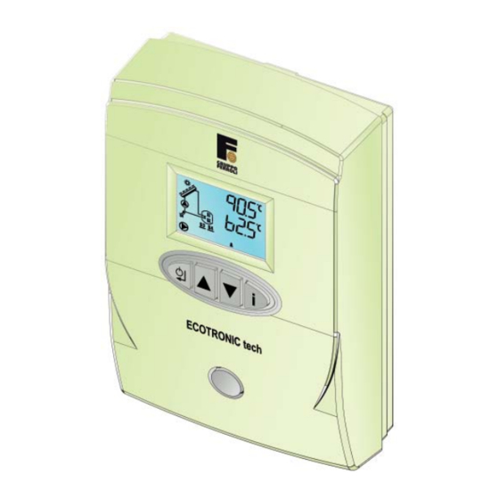
- Page 5 ECOTRONIC tech 1. PANORAMICA DEL REGOLATORE Vista frontale 1 - Display LCD retro illuminato 2 - Tastiera Cod. 3540V010 - 07/2010 (Rev. 00)
- Page 6 ECOTRONIC tech Dimensioni Cod. 3540V010 - 07/2010 (Rev. 00)
- Page 7 1 x connettore morsettiera estraibile 3 poli 1 x connettore morsettiera estraibile 11 poli 1 x connettore morsettiera estraibile 12 poli 1 x Sacchetto pt espanso per Ecotronic Tech 16x25mm 2 x Sonda PT1000 L=2500mm 1 x Sonda NTC L=2500mm...
- Page 8 ECOTRONIC tech 2. Installazione Montaggio ATTENZIONE! Prima di aprire l'involucro, assicurarsi sempre che la tensione di rete sia completamente staccata. Il montaggio deve essere effettuato esclusivamente in ambienti chiusi ed asciutti. Per garantire un funziona- mento regolare, fare attenzione che nel luogo d'installazione previsto non esistano forti campi elettromagnetici.
- Page 9 ECOTRONIC tech Assegnazione dei morsetti Sistema Base: con 1 serbatoio, 1 circolatore e 2 sonde. (No circolatore modulante, No contabilizzazione, No riscaldamento integrativo/No smaltimento calore eccedente). - Assegnazione dei morsetti e schema di principio. Simbolo Descrizione S2 (B) Sonda NTC...
- Page 10 ECOTRONIC tech Sistema 1: con 1 serbatoio, 1 circolatore e 3 sonde. (Circolatore modulante, Contabilizzazione, No riscaldamento integrativo/No smaltimento calore eccedente). - Assegnazione dei morsetti e schema di principio. Simbolo Descrizione Sonda NTC S2 (B) E' necessario acquistare la seconda...
- Page 11 ECOTRONIC tech Sistema 2A: con 1 serbatoio, 1 circolatore e 3 sonde. (No circolatore modulante, No contabilizzazione, Con riscaldamento integrativo). - Assegnazione dei morsetti e schema di principio. Simbolo Descrizione S2 (B) Sonda NTC Serbatoio inferiore S3 (C) Sonda PT1000...
- Page 12 ECOTRONIC tech Sistema 2B: con 1 serbatoio, 1 circolatore e 3 sonde. (No circolatore modulante, No contabilizzazione, Con smaltimento calore eccedente). Simbolo Descrizione - Assegnazione dei morsetti e schema di principio. S2 (B) Sonda NTC Serbatoio inferiore S3 (C) Sonda PT1000...
- Page 13 ECOTRONIC tech Sistema 3A: con 1 serbatoio, 1 circolatore e 4 sonde. (Circolatore modulante, Contabilizzazione, Con riscaldamento integrativo). Simbolo Descrizione - Assegnazione dei morsetti e schema di principio. Sonda NTC S2 (B) Serbatoio inferiore Sonda PT1000 S3 (C) Collettore Solare...
- Page 14 ECOTRONIC tech Sistema 3B: con 1 serbatoio, 1 circolatore e 4 sonde. (Circolatore modulante, Contabilizzazione, Con smaltimento calore eccedente). - Assegnazione dei morsetti e schema di principio. Simbolo Descrizione Sonda NTC S2 (B) Serbatoio inferiore E' necessario acquistare la seconda...
- Page 15 ECOTRONIC tech Sistema 4 "Est/Ovest": con 1 serbatoio, 2 circolatori e 4 sonde. (No circolatore modulante, Contabilizzazione, No riscaldamento integrativo/No smaltimento calore eccedente). - Assegnazione dei morsetti e schema di principio. Simbolo Descrizione Sonda NTC S2 (B) Serbatoio inferiore E' necessario acquistare la seconda...
- Page 16 ECOTRONIC tech Prima messa in funzione Il regolatore è impostato di fabbrica come Sistema Base. Per passare ad un altro tipo di Sistema, è possibile modifi care manualmente il parametro defi nito Impostazione del sistema (Parametro Installatore, di default pari a 0=Sistema Base) oppure avvalersi dell’Auto-confi gurazione.
- Page 17 ECOTRONIC tech 3. SISTEMI A SINGOLO PANNELLO Interfaccia utente 17 18 19 20 21 22 1 Attivato: temperatura collettore solare suffi ciente per lo 15 Attivato: temperatura bollitore corretta, normale funzio- scambio, normale funzionamento namento Lampeggiante: indicazione funzione riconoscimento Lampeggiante: indicazione funzione raff. bollitore...
- Page 18 Circolatore Solare. Se la temperatura del Sensore Bollitore S2 è maggiore o uguale al valore del parametro Temperatura massima serbatoio (Parametro installatore, di default pari a 60°C) allora il regolatore ECOTRONIC tech disattiva il Cir- colatore Solare.
- Page 19 ECOTRONIC tech Sistema 1 con 1 serbatoio, 1 circolatore e 3 sonde (Circolatore modulante, contabilizzazione, no riscaldamento integrativo/no smaltimento calore eccedente) Accensione Ogni volta che si fornisce alimentazione elettrica al regolatore il display attiverà tutti i simboli per 2 secondi;...
- Page 20 ECOTRONIC tech disattiva il Circolatore Solare. Se la temperatura del Sensore Bollitore S2 è maggiore o uguale al valore del parametro Temperatura massima serbatoio (Parametro installatore, di default pari a 60°C) allora il regolatore ECOTRONIC tech disattiva il Cir- colatore Solare.
- Page 21 Circolatore Solare. Se la temperatura del Sensore Bollitore S2 è maggiore o uguale al valore del parametro Temperatura massima serbatoio (Parametro installatore, di default pari a 60°C) allora il regolatore ECOTRONIC tech disattiva il Cir- colatore Solare.
- Page 22 Temperatura inserimento termostato (Parametro installatore, di default pari a 40°C) allora il regolatore ECOTRONIC tech attiva il Relè d’uscita collegato ai morsetti 13-14-15 (FREE CONTACT sul connettore 11 poli); mentre se la temperatura del Sensore Bollitore Superiore S1 è minore del valore del parametro Temperatura disinserimento termostato (Parametro installatore, di default pari a 45°C) allora il regolatore ECOTRONIC tech...
- Page 23 ECOTRONIC tech Sistema 3A e 3B con 1 serbatoio, 1 circolatore e 4 sonde (Circolatore modulante, Contabilizzazione, Con riscaldamento integrativo) X SISTEMA 3A (Circolatore modulante, Contabilizzazione, Con smaltimento calore eccedente) X SISTEMA 3B Accensione Ogni volta che si fornisce alimentazione elettrica al regolatore il display attiverà tutti i simboli per 2 secondi;...
- Page 24 ECOTRONIC tech disattiva il Circolatore Solare. Se la temperatura del Sensore Bollitore S2 è maggiore o uguale al valore del parametro Temperatura massima serbatoio (Parametro installatore, di default pari a 60°C) allora il regolatore ECOTRONIC tech disattiva il Cir- colatore Solare.
- Page 25 ECOTRONIC tech Modalità comuni a tutti i Sistemi a singolo pannello gestiti dal regolatore ECOTRONIC Tech Modalità off In assenza di anomalie o meno, premendo per 3 secondi il tasto ON/OFF é sempre possibile portare il regola- tore nella modalità OFF. Tutte le richieste vengono terminate, la tapparella verrà chiusa ed il display visualizza la scritta OFF.
- Page 26 Temperatura limite bollitore (Parametro installatore, di default pari a 80°C) e se la temperatura del Sensore Collettore Solare S3 è minore del valore del parametro Temperatura massima serbatoio (Parametro installatore, di default pari a 60°C) - 5°C allora il regolatore ECOTRONIC tech attiva il Circolatore Solare per raffreddare il bollitore.
- Page 27 ECOTRONIC tech questo caso oltre allo spegnimento del Circolatore Solare, il regolatore ECOTRONIC tech dovrà anche chiudere la tapparella. Per segnalare questa modalità, il simbolo Circolatore Solare verrà spento ed il simbolo Tapparella verrà acceso ed il simbolo S3 sopra il collettore inizierà a lampeggiare.
- Page 28 Sensore Bollitore S2 è maggiore del valore del parametro Temperatura disinserimento termostato (Parametro installatore, di default pari a 45°C) allora il regolatore ECOTRONIC tech disattiva il Relè d’uscita collegato ai morsetti 13-14-15 (FREE CONTACT sul connettore 11 poli).
- Page 29 ECOTRONIC tech Anomalie Display LCD spento Verifi care che il Regolatore sia alimentato elettricamente: tramite un multimetro digitale, verifi care la presenza della tensione di alimentazione ai morsetti 24 e 25. Nel caso in cui, non sia presente, verifi care il cablaggio.
- Page 30 ECOTRONIC tech Solo con SISTEMA 3 Il guasto, inteso come corto circuito o circuito aperto, del sensore non causa la disattivazione della Circolatore Solare. Il sistema deve semplicemente lavorare come se fosse impostato il Sistema 2. Risolvendo il guasto, la protezione viene immediatamente disattivata.
- Page 31 ECOTRONIC tech Menù service L’acceso al Menù Service del regolatore avviene premendo il tasto Info per 10 secondi. Premendo i tasti sarà possibile scegliere “tS”, “In”, “Hi” oppure “rE”. “tS” signifi ca Menù Parametri Trasparenti, “In” signifi ca Menù Informazioni, “Hi” signifi ca Menù History, “rE” signifi ca Reset del Menù History. Una volta selezionato il Menù, per accedervi, sarà...
- Page 32 Storico H1: rappresenta l’anomalia più recente che si è verifi cata; il dato Storico H10: rappresenta l’anomalia meno recente che si è verifi cata. N° ore funzionamento ECOTRONIC Tech (Alimentazione) tra 0 e 9999 ore...
- Page 33 ECOTRONIC tech Bilancio quantità termica (KWh) tra 0 e 9999 KWh Calcolo cumulativo eseguito solo se il circolatore é in funzione Premendo i tasti Su/Giù sarà possibile scorrere la lista delle anomalie. Per visualizzarne il valore basterà premere tasto Invio in corrispondenza del parametro stesso.
- Page 34 ECOTRONIC tech 4. SISTEMI A DOPPIO PANNELLO Interfaccia utente 19 20 21 22 1 Attivato: temperatura collettore solare suffi ciente per lo 19 Info sensore temperatura ritorno collettore solare scambio, normale funzionamento 20 Info sensore temperatura bollitore Lampeggiante: indicazione funzione riconoscimento...
- Page 35 ECOTRONIC tech disattiva il Circolatore Solare A. Se la temperatura del Sensore Bollitore S2 è maggiore o uguale al valore del parametro Temperatura massima serbatoio (Parametro installatore, di default pari a 60°C) allora il regolatore ECOTRONIC tech disattiva il Cir- colatore Solare A.
- Page 36 ECOTRONIC tech disattiva il Circolatore Solare B. Se la temperatura del Sensore Bollitore S2 è maggiore o uguale al valore del parametro Temperatura massima serbatoio (Parametro installatore, di default pari a 60°C) allora il regolatore ECOTRONIC tech disattiva il Cir- colatore Solare B.
- Page 37 ECOTRONIC tech Anomalia 81 - Sensore PT1000 Collettore Solare B S4 guasto Solo con SISTEMA 4 Il guasto, inteso come corto circuito o circuito aperto, del sensore causa la disattivazione della Circolatore Solare B. Risolvendo il guasto, la protezione viene immediatamente disattivata.
- Page 38 ECOTRONIC tech Caratteristica sensori I sensori di temperatura possono essere controllati con un multimetro digitale: scollegare il sensore dal regolatore e verifi care la corrispondenza con le seguenti tabelle. PT 1000 T (°C) R (Ω) T (°C) R (Ω) T (°C) R (Ω)
- Page 39 ECOTRONIC tech Menu service L’acceso al Menù Service del regolatore avviene premendo il tasto Info per 10 secondi. Premendo i tasti sarà possibile scegliere “tS”, “In”, “Hi” oppure “rE”. “tS” signifi ca Menù Parametri Trasparenti, “In” signifi ca Menù Informazioni, “Hi” signifi ca Menù History, “rE” signifi ca Reset del Menù History. Una volta selezionato il Menù, per accedervi, sarà...
- Page 40 Storico H1: rappresenta l’anomalia più recente che si è verifi cata; il dato Storico H10: rappresenta l’anomalia meno recente che si è verifi cata. N° ore funzionamento ECOTRONIC Tech (Alimentazione) tra 0 e 9999 ore...
- Page 41 ECOTRONIC tech Velocità circolatore media (%) Calcolo cumulativo eseguito solo se il circolatore é in funzione Bilancio quantità termica (KWh) - Pannello Solare A tra 0 e 9999 KWh Calcolo cumulativo eseguito solo se il circolatore A é in funzione Bilancio quantità...
- Page 42 ECOTRONIC tech 1. ELEMENTOS DEL REGULADOR Vista frontal 1 - Display LCD retroiluminado 2 - Teclado Cod. 3540V010 - 07/2010 (Rev. 00)
- Page 43 ECOTRONIC tech Medidas Cod. 3540V010 - 07/2010 (Rev. 00)
- Page 44 1 conector regleta extraíble 3 polos 1 conector regleta extraíble 11 polos 1 conector regleta extraíble 12 polos 1 bolsa de polietileno expandido para Ecotronic Tech 16x25 mm 2 sonda PT1000 L=2500 mm 1 sonda NTC L=2500 mm 1 bolsa con tornillos 6 sujetacables 12 tornillos autorroscantes cabeza cilíndrica 3,5x19 UNI 6954...
- Page 45 ECOTRONIC tech 2. Instalación Montaje ¡ATENCIÓN! Antes de abrir la carcasa, asegurarse de que la tensión de red esté totalmente desconectada. El dispositivo debe montarse obligatoriamente en un lugar cerrado y seco. Para garantizar un funcionamiento correcto, en el lugar de instalación no debe haber campos electromagnéticos intensos. El regulador debe poder aislarse de la red eléctrica mediante un interruptor suplementario que desconecte todos los polos (con distan-...
- Page 46 ECOTRONIC tech Asignación de los bornes Sistema base: con 1 depósito, 1 bomba solar y 2 sondas. (sin bomba solar modulante, contabilización ni apoyo a calefacción/eliminación del exceso de calor) - Asignación de los bornes y esquema general Símbolo Descripción...
- Page 47 ECOTRONIC tech Sistema 1: con 1 depósito, 1 bomba solar y 3 sondas. (con bomba solar modulante y contabilización, sin apoyo a calefacción/eliminación del exceso de calor) - Asignación de los bornes y esquema general Símbolo Descripción Sonda NTC S2 (B) Es necesario adquirir la segunda sonda depósito inferior...
- Page 48 ECOTRONIC tech Sistema 2A: con 1 depósito, 1 bomba solar y 3 sondas. (sin bomba solar modulante ni contabilización, con apoyo a calefacción) - Asignación de los bornes y esquema general Símbolo Descripción S2 (B) Sonda NTC depósito inferior S3 (C)
- Page 49 ECOTRONIC tech Sistema 2B: con 1 depósito, 1 bomba solar y 3 sondas. (sin bomba solar modulante ni contabilización, con eliminación del exceso de calor). Símbolo Descripción - Asignación de los bornes y esquema general S2 (B) Sonda NTC depósito inferior...
- Page 50 ECOTRONIC tech Sistema 3A: con 1 depósito, 1 bomba solar y 4 sondas. (con bomba solar modulante, contabilización y apoyo a calefacción) Símbolo Descripción - Asignación de los bornes y esquema general Sonda NTC S2 (B) depósito inferior Sonda PT1000...
- Page 51 ECOTRONIC tech Sistema 3B: con 1 depósito, 1 bomba solar y 4 sondas. (con bomba solar modulante, contabilización y eliminación del exceso de calor). - Asignación de los bornes y esquema general Símbolo Descripción Sonda NTC S2 (B) depósito inferior...
- Page 52 ECOTRONIC tech Sistema 4 "Este/Oeste": con 1 depósito, 2 bombas solares y 4 sondas. (sin bomba solar modulante, contabilización ni apoyo a calefacción/eliminación del exceso de calor) - Asignación de los bornes y esquema general Símbolo Descripción Sonda NTC S2 (B) depósito inferior...
- Page 53 ECOTRONIC tech Primera puesta en marcha El regulador se entrega confi gurado como sistema base. Para pasar a otro tipo de sistema, es posible modifi car manualmente el parámetro Confi guración del sistema (parámetro de instalador, por defecto igual a 0=sistema base) o utilizar la autoconfi guración.
- Page 54 ECOTRONIC tech 3. SISTEMAS DE UN SOLO PANEL Interfaz de usuario 17 18 19 20 21 22 1 Encendido: temperatura colector sufi ciente para conmu- 16 Velocidad actual bomba (A=mínima, E=máxima) tación, funcionamiento normal 17 Encendido: sensor acumulador superior correcto, fun- Parpadeante: función de reconocimiento de colector...
- Page 55 S3 y el sensor del acumulador S2 es mayor o igual que el parámetro Diferencial de temperatura activación (parámetro de instalador, por defecto igual a 6 °C), el regulador ECOTRONIC tech activa la bomba. Para indicar este modo de funcionamiento, se enciende el símbolo Bomba.
- Page 56 S3 y el sensor del acumulador S2 es mayor o igual que el parámetro Diferencial de temperatura activación (parámetro de instalador, por defecto igual a 6 °C), el regulador ECOTRONIC tech activa la bomba. Para indicar este modo de funcionamiento, se enciende el símbolo Bomba.
- Page 57 ECOTRONIC tech NOTA: Cuando se activa la bomba solar, aunque el regulador ECOTRONIC tech no deba activar la velocidad 5 (potencia máxima, 100%), en el primer segundo de funcionamiento la bomba funciona igualmente a velocidad 5 (potencia máxima, 100%). Si el parámetro Funcionamiento bomba solar (parámetro de instalador, por defecto igual a 1=modulante) se hace igual a 0, no hay modulación: la bomba solar funciona en on/off según los algoritmos normales de activación y...
- Page 58 Temperatura cierre termostato (parámetro de instalador, por defecto igual a 40 °C), el regulador ECOTRONIC tech activa el relé de salida conectado a los bornes 13-14-15 (contacto libre en el conector de 11 polos). Si la temperatura del sensor del acumulador superior S1 es mayor que el parámetro Temperatura apertura termostato (parámetro de instalador, por defecto igual a 45 °C), el regulador ECOTRONIC tech desactiva el relé...
- Page 59 Temperatura cierre termostato (parámetro de instalador, por defecto igual a 40 °C), el regulador ECOTRONIC tech activa el relé de salida conectado a los bornes 13-14-15 (contacto libre en el conector de 11 polos). Si la temperatura del sensor del acumulador superior S1 es menor que el parámetro Temperatura apertura termostato (parámetro de instalador, por defecto igual a 45 °C), el regulador ECOTRONIC tech desactiva el relé...
- Page 60 S3 y el sensor del acumulador S2 es mayor o igual que el parámetro Diferencial de temperatura activación (parámetro de instalador, por defecto igual a 6 °C), el regulador ECOTRONIC tech activa la bomba. Para indicar este modo de funcionamiento, se enciende el símbolo Bomba.
- Page 61 Temperatura cierre termostato (parámetro de instalador, por defecto igual a 40 °C), el regulador ECOTRONIC tech activa el relé de salida conectado a los bornes 13-14-15 (contacto libre en el conector de 11 polos). Si la temperatura del sensor del acumulador superior S1 es mayor que el parámetro Temperatura apertura termostato (parámetro de instalador, por defecto igual a 45 °C), el regulador ECOTRONIC tech desactiva el relé...
- Page 62 ECOTRONIC tech Modos comunes a todos los sistemas de un solo panel controlados por el regulador ECOTRONIC Tech Modo off En presencia o ausencia de anomalías, presionando la tecla ON/OFF durante 3 segundos se pone el regulador en OFF. Todas las demandas se concluyen, la persiana se cierra y en el display aparece la palabra OFF.
- Page 63 S3 es mayor que el parámetro Temperatura colector activación enfriamiento sistema (parámetro de instalador, por defecto igual a 120 °C), el regulador ECOTRONIC tech activa la bomba para enfriar el colector. Para indicar este modo de funcionamiento, el símbolo Panel solar comienza a parpadear.
- Page 64 Temperatura límite colector (parámetro de instalador, por defecto igual a 140 °C); en este caso, además de apagar la bomba solar, el regulador ECOTRONIC tech cierra la persiana. Para indicar este modo de funcionamiento el símbolo Bomba se apaga, el símbolo Persiana se enciende y el símbolo S3 sobre el colector comienza a parpadear.
- Page 65 S2 es mayor que el parámetro Temperatura apertura termostato (parámetro de instalador, por defecto igual a 45 °C), el regulador ECOTRONIC tech desactiva el relé de salida conectado a los bornes 13-14-15 (contacto libre en el conector de 11 polos).
- Page 66 ECOTRONIC tech Anomalías Display LCD apagado Controlar que el regulador reciba alimentación eléctrica: verifi car con un multímetro digital que haya tensión de alimentación en los bornes 24 y 25. Si no hay tensión, controlar el cableado. Si hay tensión sufi ciente (195 – 253 Vca), controlar el fusible. El fusible está dentro del regulador: para el acceso, realizar los puntos 1 y 2 del apartado Montaje del regulador.
- Page 67 ECOTRONIC tech Solo con SISTEMA 3 El fallo del sensor, entendido como cortocircuito o circuito abierto, no causa la desactivación de la bomba. La instalación funciona como si estuviese confi gurado el sistema 2. Cuando se resuelve el fallo, la protección se desactiva inmediatamente.
- Page 68 ECOTRONIC tech Menù service Para entrar en el menú Service del regulador hay que pulsar la tecla Info durante 10 segundos. Presionando las teclas , es posible seleccionar “tS”, “In”, “Hi” o “rE”. "tS" signifi ca menú parámetros modifi cables, "In"...
- Page 69 El microprocesador puede memorizar las horas totales con el regulador alimentado (Ht), las 10 últimas anomalías y otras informaciones; el dato Historial H1 representa la anomalía más reciente; el dato Historial H10 representa la anomalía menos reciente. Horas de funcionamiento de ECOTRONIC Tech (alimentación) de 0 a 9999 horas Código de la anomalía Código de la anomalía...
- Page 70 ECOTRONIC tech Velocidad media bomba solar (%) 0-100% El cálculo acumulativo se realiza sólo si la bomba solar está en marcha. Balance de la cantidad de calor (kWh) de 0 a 9999 kWh El cálculo acumulativo se realiza sólo si la bomba solar está en marcha.
- Page 71 ECOTRONIC tech Balance de la cantidad de calor (contabilización) El regulador calcula la energía acumulada sólo si la bomba solar está en marcha: el valor se visualiza mediante el parámetro BIL en el menú Historial (ver el apartado Menú Service).
- Page 72 ECOTRONIC tech 4. SISTEMAS DE DOS PANELES Interfaz de usuario 19 20 21 22 1 Encendido: temperatura colector sufi ciente para conmu- 21 Info sensor temperatura colector A tación, funcionamiento normal 22 Info sensor temperatura colector B Parpadeante: función de reconocimiento de colector 24 Encendido: temperatura colector B correcta, funciona- frío...
- Page 73 A S3 y el sensor del acumulador S2 es mayor o igual que el parámetro Diferencial de temperatura ac- tivación (parámetro de instalador, por defecto igual a 6 °C), el regulador ECOTRONIC tech activa la bomba A. Para indicar este modo de funcionamiento, se enciende el símbolo Bomba junto a la letra A.
- Page 74 ECOTRONIC tech (parámetro de instalador, por defecto igual a 60 °C), el regulador ECOTRONIC tech desactiva la bomba B. Para indicar este modo de funcionamiento, se apaga el símbolo Bomba junto a la letra B. Modos comunes a todos los sistemas de dos paneles controlados por el regulador ECOTRONIC Tech Modo off En presencia o ausencia de anomalías, presionando la tecla ON/OFF durante 3 segundos se pone el regulador...
- Page 75 ECOTRONIC tech Anomalía 81 - Sensor PT1000 colector B S4 averiado Solo con SISTEMA 4 El fallo del sensor, entendido como cortocircuito o circuito abierto, hace que se desactive la bomba solar B. Cuando se resuelve el fallo, la protección se desactiva inmediatamente.
- Page 76 ECOTRONIC tech Características de los sensores Los sensores de temperatura se pueden controlar con un multímetro digital, desconectar el sensor del regulador y contrastar los valores con las tablas siguientes. PT 1000 T (°C) R (Ω) T (°C) R (Ω) T (°C)
- Page 77 ECOTRONIC tech Menù service Para entrar en el menú Service del regulador hay que pulsar la tecla Info durante 10 segundos. Presionando las teclas es posible seleccionar “tS”, “In”, “Hi” o “rE”. "tS" signifi ca menú parámetros modifi cables, "In"...
- Page 78 El microprocesador puede memorizar las horas totales con el regulador alimentado (Ht), las 10 últimas anomalías y otras informaciones; el dato Historial H1 representa la anomalía más reciente; el dato Historial H10 representa la anomalía menos reciente. Horas de funcionamiento de ECOTRONIC Tech (alimentación) de 0 a 9999 horas Código de la anomalía Código de la anomalía...
- Page 79 ECOTRONIC tech Balance de la cantidad de calor (kWh) - Panel solar A de 0 a 9999 kWh El cálculo acumulativo se realiza sólo si la bomba solar A está en marcha. Balance de la cantidad de calor (kWh) - Panel solar B...
-
Page 80: Overview Of Regulator
ECOTRONIC tech 1. OVERVIEW OF REGULATOR Front view 1 - Backlit LCD display 2 - Keyboard Cod. 3540V010 - 07/2010 (Rev. 00) -
Page 81: Dimensions
ECOTRONIC tech Dimensions Cod. 3540V010 - 07/2010 (Rev. 00) -
Page 82: Ecotronic Tech Kit List
1 x removable 3-pin terminal block connector 1 x removable 11-pin terminal block connector 1 x removable 12-pin terminal block connector 1 x PT foam bag for Ecotronic Tech 16x25mm 2 x PT1000 probe L=2500mm 1 x NTC probe L=2500mm... -
Page 83: Installation
ECOTRONIC tech 2. Installation Mounting ATTENTION! Always make sure the power is completely disconnected before opening the enclosure. Installation must only be carried out in closed and dry places. To ensure proper operation, make sure strong electromagnetic fi elds do not exist in the place of installation. The regulator must be separated from the electric mains by means of an additional device (with disconnection distance of at least 3 mm on all poles), or with a disconnecting device complying with the current standards. -
Page 84: Assigning Of Terminals
ECOTRONIC tech Assigning of terminals Basic System: with 1 tank, 1 circulating pump and 2 probes. (No modulating circulating pump, No calculation, No supplementary heating/No elimination of excess heat). - Assigning of terminals and main diagram. Symbol Description S2 (B) - Page 85 ECOTRONIC tech System 1: with 1 tank, 1 circulating pump and 3 probes. (Modulating circulating pump, Calculation, No supplementary heating/No elimination of excess heat). - Assigning of terminals and main diagram. Symbol Description Lower tank S2 (B) The second accessory NTC probe must...
- Page 86 ECOTRONIC tech System 2A: with 1 tank, 1 circulating pump and 3 probes. (No modulating circulating pump, No calculation, With supplementary heating). - Assigning of terminals and main diagram. Symbol Description S2 (B) Lower tank NTC probe S3 (C) Solar Collector...
- Page 87 ECOTRONIC tech System 2B: with 1 tank, 1 circulating pump and 3 probes. (No modulating circulating pump, No calculation, With elimination of excess heat). Symbol Description - Assigning of terminals and main diagram. S2 (B) Lower tank NTC probe S3 (C)
- Page 88 ECOTRONIC tech System 3A: with 1 tank, 1 circulating pump and 4 probes. (Modulating circulating pump, Calculation, With supplementary heating). Symbol Description - Assigning of terminals and main diagram. Lower tank S2 (B) NTC probe Solar Collector S3 (C) PT1000 probe...
- Page 89 ECOTRONIC tech System 3B: with 1 tank, 1 circulating pump and 4 probes. (Modulating circulating pump, Calculation, With elimination of excess heat). - Assigning of terminals and main diagram. Symbol Description Lower tank S2 (B) NTC probe The second accessory NTC probe must...
- Page 90 ECOTRONIC tech System 4 "East/West": with 1 tank, 2 circulating pumps and 4 probes. (No modulating circulating pump, Calculation, No supplementary heating/No elimination of excess heat). - Assigning of terminals and main diagram. Symbol Description Lower tank S2 (B) NTC probe...
-
Page 91: First Startup
ECOTRONIC tech First startup The regulator is factory-set as a Basic System. To change to another type of System, it is possible to manually modify the parameter defi ned System setting (Installer parameter, default equal to 0=Basic System) or make use of Auto-confi guration. -
Page 92: Single-Panel Systems
ECOTRONIC tech 3. SINGLE-PANEL SYSTEMS User interface 17 18 19 20 21 22 1 Activated: solar collector temperature suffi cient for 17 Activated: upper hot water tank sensor ok, normal ope- exchange, normal operation ration Flashing: solar collector cold recognition function... -
Page 93: Operation
Solar Circulating Pump. If the temperature of Hot Water Tank Sensor S2 is higher than or equal to the Tank max. temperature parameter value (Installer parameter, default equal to 60°C) then the ECOTRONIC tech regulator deactivates the Solar Circulating Pump. - Page 94 Collector Sensor S3 and the temperature of Hot Water Tank Sensor S2 is greater than or equal to the Activation temperature differential parameter value (Installer parameter, default equal to 6°C) then the ECOTRONIC tech regulator activates the Solar Circulating Pump.
- Page 95 To signal this mode, the symbol E will be lit. NB: If, at the moment of Solar Circulating Pump activation, the ECOTRONIC tech regulator does not have to set speed 5 (Max. power, 100%), the Solar Circulating Pump will work in any case at speed 5 (Max. power, 100%) in the fi...
- Page 96 Solar Circulating Pump. If the temperature of Hot Water Tank Sensor S2 is higher than or equal to the Tank max. temperature parameter value (Installer parameter, default equal to 60°C) then the ECOTRONIC tech regulator deactivates the Solar Circulating Pump.
- Page 97 During normal operation, if the temperature of Upper Hot Water Tank Sensor S1 is higher than the Thermostat activation temperature parameter value (Installer parameter, default equal to 40°C) then the ECOTRONIC tech regulator activates the output Relay connected to terminals 13-14-15 (FREE CONTACT on the 11-pin connector);...
- Page 98 Collector Sensor S3 and the temperature of Hot Water Tank Sensor S2 is greater than or equal to the Activation temperature differential parameter value (Installer parameter, default equal to 6°C) then the ECOTRONIC tech regulator activates the Solar Circulating Pump.
- Page 99 To signal this mode, the symbol E will be lit. NB: If, at the moment of Solar Circulating Pump activation, the ECOTRONIC tech regulator does not have to set speed 5 (Max. power, 100%), in the fi rst second of operation the Solar Circulating Pump will in any case work at speed 5 (Max.
- Page 100 ECOTRONIC tech Modes common to all single-panel Systems managed by the ECOTRONIC tech regulator Off mode If there are no faults it is always possible to press the ON/OFF button for 3 seconds to switch the regulator to Off mode. All demands are terminated, the shutter will be closed and the display shows the message OFF.
- Page 101 S3 is lower than the Hot water tank limit temperature parameter value (Installer parameter, default equal to 80°C) – 5°C then the ECOTRONIC tech regulator activates the Solar Circulating Pump to cool the hot water tank. To signal this mode, the Hot Water Tank symbol will start fl ashing.
- Page 102 The Solar Circulating Pump will be deactivated if the temperature of Solar Collector Sensor S3 becomes higher than or equal to the Collector limit temperature parameter value (Installer parameter, default equal to 140°C); in this case, as well as shutting down the Solar Circulating Pump, the ECOTRONIC tech regulator must also close the shutter.
- Page 103 Hot Water Tank Sensor S2 is higher than the Thermostat deactivation temperature parameter value (Installer parameter, default equal to 45°C) then the ECOTRONIC tech regulator deactivates the output Relay connected to terminals 13-14-15 (FREE CONTACT on the 11-pin connector).
-
Page 104: Faults
ECOTRONIC tech Faults LCD display off Make sure the regulator is powered: using a digital multimeter, check the presence of voltage at terminals 24 and 25. In case of no voltage, check the wiring. In case of suffi cient voltage (Range 195 – 253 Vac), check the fuse. The fuse is located inside the regulator: to... - Page 105 ECOTRONIC tech The sensor fault, understood as a short circuit or open circuit, does not cause deactivation of the Solar Circulating Pump. The system must simply work as though the System 2 were set. On eliminating the fault, the protection is immediately deactivated.
-
Page 106: Service Menu
ECOTRONIC tech Service menu The regulator Service Menu is accessed by pressing the Info button for 10 seconds. Press the buttons to select “tS”, “In”, “Hi” or “rE”. "tS" means Transparent Parameters Menu, "In" Information Menu, "Hi" History Menu, and "rE" History Menu Reset. After selecting the Menu, press the Info button to access it. - Page 107 The microprocessor can memorise the total hours with regulator fed (Ht), the last 10 boiler faults and other infor- mation; the History datum item H1: represents the most recent fault that occurred; the History datum item H10: represents the least recent fault that occurred. No. hours ECOTRONIC Tech operation (Supply) between 0 and 9999 hours Fault code...
-
Page 108: Thermal Quantity Balance (Calculation)
ECOTRONIC tech No. litres solar circuit (litres) between 0 and 9999 litres Only with Flowmeter connected and activated Average circulating pump speed (%) 0-100% Cumulative calculation performed only if the circulating pump is working Thermal Quantity Balance (kWh) between 0 and 9999 kWh Cumulative calculation performed only if the circulating pump is working Press the Up/Down buttons to scroll the list of faults. -
Page 109: Double-Panel System
ECOTRONIC tech 4. DOUBLE-PANEL SYSTEM User interface 19 20 21 22 Activated: solar collector temperature suffi cient for 19 Solar collector return temperature sensor info exchange, normal operation 20 Hot water tank temperature sensor info 21 Solar collector A temperature sensor info... -
Page 110: Operation
Sensor S3 and the temperature of Hot Water Tank Sensor S2 is greater than or equal to the activation tempera- ture Differential parameter value (Installer parameter, default equal to 6°C) then the ECOTRONIC tech regulator activates the Solar Circulating Pump A. - Page 111 Solar Circulating Pump B. If the temperature of Hot Water Tank Sensor S2 is higher than or equal to the Tank max. temperature parameter value (Installer parameter, default equal to 60°C) then the ECOTRONIC tech regulator deactivates Solar Circu- lating Pump B.
-
Page 112: Faults
ECOTRONIC tech Functions common to all double-panel Systems managed by the ECOTRONIC tech regulator The ECOTRONIC Tech manages all the functions of the single-panel systems in a simultaneous way on panel A and/or Solar Panel B. Faults LCD display off Make sure the Regulator is powered: using a digital multimeter, check the presence of voltage at terminals 24 and 25. - Page 113 ECOTRONIC tech Fault 85 - Regulator confi guration fault Make sure parameter P26 is set to 1. Fault 87 - Regulator confi guration fault Make sure parameter P25 is set to 0. Sensor characteristics The temperature sensors can be checked with a digital multimeter: disconnect the sensor from regulator and check correspondence with the following tables.
-
Page 114: Service Menu
ECOTRONIC tech Service menu The regulator Service Menu is accessed by pressing the Info button for 10 seconds. Press the buttons to select “tS”, “In”, “Hi” or “rE”. "tS" means Transparent Parameters Menu, "In" Information Menu, "Hi" History Menu, and "rE" History Menu Reset. After selecting the Menu, press the Info button to access it. - Page 115 The microprocessor can memorise the total hours with regulator fed (Ht), the last 10 faults and other information; the History datum item H1: represents the most recent fault that occurred; the History datum item H10: represents the least recent fault that occurred. No. hours ECOTRONIC Tech operation (Supply) between 0 and 9999 hours Fault code...
-
Page 116: Thermal Quantity Balance (Calculation)
ECOTRONIC tech Average circulating pump speed (%) Cumulative calculation performed only if the circulating pump is working Thermal Quantity Balance (kWh) - Solar Panel A between 0 and 9999 kWh Cumulative calculation performed only if circulating pump A is working... -
Page 117: Panoramique Du Régulateur
ECOTRONIC tech 1. PANORAMIQUE DU RÉGULATEUR Vue de face 1 - Affi cheur LCD rétro-éclairé 2 - Clavier Cod. 3540V010 - 07/2010 (Rev. 00) -
Page 118: Dimensions
ECOTRONIC tech Dimensions Cod. 3540V010 - 07/2010 (Rev. 00) -
Page 119: Liste Kit Ecotronic Tech
1 x connecteur bornier extractible 3 pôles 1 x connecteur bornier extractible 11 pôles 1 x connecteur bornier extractible 12 pôles 1 x Sac pt expansé pour Ecotronic Tech 16x25mm 2 x Sonde PT1000 L=2500mm 1 x Sonde NTC L=2500mm 1 x sachet de vis 6 x bloque-câble... -
Page 120: Installation
ECOTRONIC tech 2. Installation Montage ATTENTION ! Avant d'ouvrir l'habillage, vérifier que le courant est complètement coupé. Le montage doit être effectué exclusivement dans un local fermé et sec. Pour garantir le bon fonctionnement de l'appareil, vérifi er que le lieu d'installation n'est pas sujet à de forts champs magnétiques. Le régulateur doit être séparé... -
Page 121: Bornage
ECOTRONIC tech Bornage Système Base : avec 1 réservoir, 1 circulateur et 2 sondes. (pas de circulateur modulant, pas de comptabilisation, pas de chauffage auxiliaire/pas d'évacuation de la chaleur en excès). - Bornage et schéma de principe. Sym- Description bole... - Page 122 ECOTRONIC tech Système 1: avec 1 réservoir, 1 circulateur et 3 sondes. (Circulateur modulant, Comptabilisation, Pas chauffage auxiliaire/ pas évacuation chaleur en excédent ). - Bornage et schéma de principe. Symbole Description Sonde NTC S2 (B) Il est nécessaire d’acheter la seconde Réservoir inférieur...
- Page 123 ECOTRONIC tech Système 2A : avec 1 réservoir, 1 circulateur et 3 sondes. (Pas circulateur modulant, Pas Comptabilisation, avec chauffage auxiliaire). - Bornage et schéma de principe. Sym- Description bole S2 (B) Sonde NTC Réservoir inférieur S3 (C) Sonde PT1000...
- Page 124 ECOTRONIC tech Système 2B : avec 1 réservoir, 1 circulateur et 3 sondes. (Pas circulateur modulant, Pas Comptabilisation, avec évacuation chaleur en excédent). Sym- Description - Bornage et schéma de principe. bole S2 (B) Sonde NTC Réservoir inférieur S3 (C)
- Page 125 ECOTRONIC tech Système 3A : avec 1 réservoir, 1 circulateur et 4 sondes. (Circulateur modulant, Comptabilisation, avec chauffage auxiliaire). Symbole Description - Bornage et schéma de principe. Sonde NTC S2 (B) Réservoir inférieur Sonde PT1000 S3 (C) Il est nécessaire d’acheter la seconde...
- Page 126 ECOTRONIC tech Système 3B : avec 1 réservoir, 1 circulateur et 4 sondes. (Circulateur modulant, Comptabilisation, avec évacuation chaleur en excédent). - Bornage et schéma de principe. Symbole Description Sonde NTC S2 (B) Réservoir inférieur Il est nécessaire d’acheter la seconde...
- Page 127 ECOTRONIC tech Système 4 "Est/Ouest": avec 1 réservoir, 2 circulateurs et 4 sondes. (pas de circulateur modulant, comptabilisation, pas de chauffage auxiliaire/pas d'évacuation de la chaleur en excès). Symbole Description - Bornage et schéma de principe. Sonde NTC S2 (B) Réservoir inférieur...
-
Page 128: Première Mise En Fonction
ECOTRONIC tech Première mise en fonction Le régulateur est programmé d'usine comme système base. Pour passer à un autre type de système, il est possible de modifi er manuellement le paramètre défi ni dans confi gu- ration du système (Paramètre Installateur, par défaut égal à 0=Système Base) ou utiliser l'auto-confi guration. -
Page 129: Système À Panneau Simple
ECOTRONIC tech 3. SYSTÈME À PANNEAU SIMPLE Interface usager 17 18 19 20 21 22 1 Activé : température collecteur solaire suffi sant pour 15 Activé : température ballon chaudière correcte, fonc- l'échange, fonctionnement normal tionnement normal Clignotant : Indication fonction reconnaissance col- Clignotant : Indication fonction refr. -
Page 130: Fonctionnement
(Paramètre installateur, par défaut 60°C) et si la différence (positive) entre la température du capteur collecteur solaire S3 et la température du capteur ballon S2 dépasse ou égale la valeur du paramètre différentiel de température activation (Paramètre installateur, par défaut 6°C) alors le régulateur ECOTRONIC tech active le circulateur solaire. - Page 131 (Paramètre installateur, par défaut 60°C) et si la différence (positive) entre la température du capteur collecteur solaire S3 et la température du capteur ballon S2 dépasse ou égale la valeur du paramètre différentiel de température activation (Paramètre installateur, par défaut 6°C) alors le régulateur ECOTRONIC tech active le circulateur solaire.
- Page 132 E sera allumé. N.B : Si au moment de l'activation du circulateur solaire, le régulateur ECOTRONIC tech n'enclenche pas la vitesse 5 (puissance maximum, 100%), au cours de la première seconde de fonctionnement le circulateur solaire travaillera à...
- Page 133 S1 dépasse la valeur du paramètre température désactivation thermostat (Paramètre installateur, par défaut 45°C) alors le régulateur ECOTRONIC tech désactive le relais de sortie relié aux bornes 13-14-15 (FREE CONTACT sur le connecteur 11 pôles).
- Page 134 S1 est inférieure à la valeur du paramètre température désactivation thermostat (Paramètre installateur, par défaut 45°C) alors le régulateur ECOTRONIC tech désactive le relais de sortie relié aux bornes 13-14-15 (FREE CONTACT sur le connecteur 11 pôles).
- Page 135 (Paramètre installateur, par défaut 60°C) et si la différence (positive) entre la température du capteur collecteur solaire S3 et la température du capteur ballon S2 dépasse ou égale la valeur du paramètre différentiel de température activation (Paramètre installateur, par défaut 6°C) alors le régulateur ECOTRONIC tech active le circulateur solaire.
- Page 136 Pour signaler cette modalité, le symbole E sera allumé. N.B : Si au moment de l’activation du circulateur solaire, le régulateur ECOTRONIC tech n'enclenche pas la vitesse 5 (puissance maximum, 100%), au cours de la première seconde de fonctionnement le circulateur solaire travaillera à...
- Page 137 ECOTRONIC tech Modalités communes à tous les systèmes gérés par le régulateur ECOTRONIC Tech Mode OFF En absence d'anomalie, en appuyant 3 secondes les touches ON/OFF il est toujours possible de porter le régu- lateur en mode OFF. Toutes les demandes sont terminées, le rideau sera fermé et l'affi cheur visualise OFF.
- Page 138 (paramètre installateur, par défaut 80°C) et si la température du capteur collecteur solaire S3 dépasse la valeur du paramètre température collecteur activation fonction refroidissement système (Paramètre installateur, par défaut 120°C) le régulateur ECOTRONIC tech active le circulateur solaire pour refroidir le collecteur. Pour signaler cette modalité, le symbole Panneau Solaire commencera à clignoter.
- Page 139 (paramètre installateur, par défaut 140°C) ; dans ce cas, outre l'extinction du circulateur solaire, le régulateur ECOTRONIC tech devra fermer le rideau. Pour signaler cette modalité, le symbole circulateur solaire sera éteint, le symbole rideau sera allumé et le symbole S3 au-dessus du collecteur commencera à...
- Page 140 S2 dépasse la valeur du paramètre température désactivation thermostat (Paramètre installateur, par défaut 45°C) alors le régulateur ECOTRONIC tech désactive le relais de sortie relié aux bornes 13-14-15 (FREE CONTACT sur le connecteur 11 pôles).
-
Page 141: Anomalies
ECOTRONIC tech Anomalies Affi cheur LCD éteint Vérifi er que le régulateur est alimenté électriquement : avec un multimètre numérique, vérifi er la présence de tension d'alimentation aux bornes 24 et 25. A défaut, vérifi er le câblage. En présence de tension suffi sante (plage 195 – 253 Vac ), vérifi er l'état du fusible. Le fusible se trouve à l'intérieur du régulateur : pour y accéder suivre les points 1 et 2 du paragraphe correspondant au montage du régulateur. - Page 142 ECOTRONIC tech La panne, entendue comme court-circuit ou circuit-ouvert, du capteur provoque la désactivation du circulateur solaire. Le système doit simplement travailler comme si le Système 2 était programmé. En résolvant la panne, la protection est immédiatement désactivée. Pour signaler cette anomalie, le symbole S4 sera désactivé et le symbole anomalie, le symbole S4 et la backlight commenceront à...
-
Page 143: Menu Service
ECOTRONIC tech Menu service L'accès au menu service du régulateur se fait en appuyant les touches Info pendant 10 secondes. Appuyer sur les touches , pour sélectionner “tS”, “In”, “Hi” ou “rE "tS" = Menu Paramètres Transparents ; "In" = Menu Informations ;... - Page 144 10 anomalies et autres informations ; La donnée Historique H1: représente l'anomalie la plus récente qui s'est produite ; la donnée Historique H10: représente l'anomalie la plus ancienne. N° heures de fonctionnement ECOTRONIC Tech (Alimentation) entre 0 et 9999...
-
Page 145: Bilan Quantité Thermique (Comptabilisation)
ECOTRONIC tech N° litres circuit solaire (litres) entre 0 et 9999 litres Uniquement avec débitmètre relié et activé Vitesse moyenne circulateur (%) 0-100% Calcul cumulatif effectué uniquement si le circulateur fonctionne Bilan quantité thermique (KWh) entre 0 et 9999 KWh Calcul cumulatif effectué... -
Page 146: Systèmes À Double Panneau
ECOTRONIC tech 4. SYSTÈMES À DOUBLE PANNEAU Interface usager 19 20 21 22 Activé : température collecteur solaire suffi sant pour l'échange, fonctionnement normal 19 Info capteur température retour collecteur solaire 20 Info capteur température ballon Clignotant : Indication fonction reconnaissance col- 21 Info capteur température collecteur solaire A... -
Page 147: Fonctionnement
(Paramètre installateur, par défaut 60°C) et si la différence (positive) entre la température du capteur collecteur solaire A S3 et la température du capteur ballon S2 dépasse ou égale la valeur du paramètre différentiel de température activation (Paramètre installateur, par défaut 6°C) alors le régulateur ECOTRONIC tech active le circulateur solaire A. - Page 148 Si la température du capteur ballon S2 dépasse ou égale la valeur du paramètre température maximum réservoir (Paramètre installateur, par défaut 60°C) alors le régulateur ECOTRONIC tech désactive le circulateur solaire B. Pour signaler cette modalité, le symbole circulateur solaire sera éteint simultanément au symbole B.
-
Page 149: Anomalies
Fonctions communes à tous les systèmes à double panneau gérés par le régulateur ECOTRONIC Tech L'ECOTRONIC Tech gère toutes les fonctions des systèmes à panneau simple de façon simultanée sur le pan- neau A et/ou sur le panneau solaire B. - Page 150 ECOTRONIC tech Anomalie 85 - Anomalie confi guration régulateur Vérifi er que le paramètre P26 est programmé sur 1. Anomalie 87 - Anomalie confi guration régulateur Vérifi er que le paramètre P25 est programmé sur 0. Caractéristique capteurs Les capteurs de température peuvent être contrôlés avec un multimètre numérique : débrancher le capteur du régulateur et vérifi...
-
Page 151: Menu Service
ECOTRONIC tech Menu service L'accès au menu service du régulateur se fait en appuyant les touches Info pendant 10 secondes. Appuyer sur les touches , pour sélectionner “tS”, “In”, “Hi” ou “rE "tS" = Menu Paramètres Transparents ; "In" = Menu Informations ;... - Page 152 10 anomalies et autres informations ; La donnée Historique H1: représente l'anomalie la plus récente qui s'est produite ; la donnée Historique H10: représente l'anomalie la plus ancienne. N° heures de fonctionnement ECOTRONIC Tech (Alimentation) entre 0 et 9999...
-
Page 153: Bilan Quantité Thermique (Comptabilisation)
ECOTRONIC tech Temp. maxi. S4: capteur PT1000 collecteur solaire B (°C) entre 01 et 180 °C Uniquement avec Système 4 N° litres circuit solaire (litres) entre 0 et 9999 litres Uniquement avec débitmètre relié et activé Vitesse moyenne circulateur (%) Calcul cumulatif effectué... -
Page 154: Overzicht Van De Regelaar
ECOTRONIC tech 1. OVERZICHT VAN DE REGELAAR Vooraanzicht 1 - LCD display met achtergrondverlichting 2 - Toetsenbord Cod. 3540V010 - 07/2010 (Rev. 00) -
Page 155: Afmetingen
ECOTRONIC tech Afmetingen Cod. 3540V010 - 07/2010 (Rev. 00) -
Page 156: Lijst Kit Ecotronic Tech
1 x verwijderbare 3-polige connector klemmenbord 1 x verwijderbare 11-polige connector klemmenbord 1 x verwijderbare 12-polige connector klemmenbord 1 x Zakje van Polyurethaanschuim voor Ecotronic Tech 16x25mm 2 x Sonde PT1000 L=2500mm 1 x Sonde NTC L=2500mm 1 x zakje met schroeven 6 x kabelklemmen 12 x zelftappers TC 3.5x19 UNI6954... -
Page 157: Installatie
ECOTRONIC tech 2. Installatie Montage LET OP! Controleer altijd eerst of de stroom volledig is uitgeschakeld alvorens de behuizing open te maken. Monteer de regelaar uitsluitend in een droge en gesloten ruimte. Met het oog op de correcte werking mogen er op de plaats van installatie geen sterke elektromagnetische velden aanwezig zijn. -
Page 158: Toewijzing Van De Klemmen
ECOTRONIC tech Toewijzing van de klemmen Basissysteem: met 1 reservoir, 1 circulatiepomp en 2 sondes. (Geen modulerende circulatiepomp, Geen berekening, geen aanvullende verwarming/Geen afvoer overtollige warmte). - Toewijzing van de klemmen en aansluitschema. Sym- Beschrijving bool S2 (B) Sonde NTC... - Page 159 ECOTRONIC tech Systeem 1: met 1 reservoir, 1 circulatiepomp en 3 sondes. (Modulerende circulatiepomp, Berekening, Geen aanvullende verwarming/Geen afvoer overtollige warmte). - Toewijzing van de klemmen en aansluitschema. Symbool Beschrijving Het is noodzakelijk de bijkomende twee- Sonde NTC S2 (B)
- Page 160 ECOTRONIC tech Systeem 2A: met 1 reservoir, 1 circulatiepomp en 3 sondes. (Geen modulerende circulatiepomp, Geen berekening, Met aanvullende verwarming). - Toewijzing van de klemmen en aansluitschema. Sym- Beschrijving bool S2 (B) Sonde NTC Onderste reservoir S3 (C) Sonde PT1000...
- Page 161 ECOTRONIC tech Systeem 2B: met 1 reservoir, 1 circulatiepomp en 3 sondes. (Geen modulerende circulatiepomp, Geen berekening, Met afvoer overtollige warmte). Sym- Beschrijving - Toewijzing van de klemmen en aansluitschema. bool S2 (B) Sonde NTC Onderste reservoir S3 (C) Sonde PT1000...
- Page 162 ECOTRONIC tech Systeem 3A: met 1 reservoir, 1 circulatiepomp en 4 sondes. (Modulerende circulatiepomp, Berekening, Met aanvullende verwarming). Symbool Beschrijving - Toewijzing van de klemmen en aansluitschema. Sonde NTC S2 (B) Onderste reservoir Sonde PT1000 S3 (C) Zonnecollector Het is noodzakelijk de bijkomende twee-...
- Page 163 ECOTRONIC tech Systeem 3B: met 1 reservoir, 1 circulatiepomp en 4 sondes. (Modulerende circulatiepomp, Berekening, Met afvoer overtollige warmte). - Toewijzing van de klemmen en aansluitschema. Symbool Beschrijving Sonde NTC S2 (B) Onderste reservoir Sonde PT1000 S3 (C) Het is noodzakelijk de bijkomende twee-...
- Page 164 ECOTRONIC tech Systeem 4 "Oosten/Westen": met 1 reservoir, 2 circulatiepompen en 4 sondes. (Geen modulerende circulatiepomp, Berekening, Geen aanvullende verwarming/Geen afvoer overtollige warmte). - Toewijzing van de klemmen en aansluitschema. Symbool Beschrijving Sonde NTC S2 (B) Onderste reservoir Sonde PT1000...
-
Page 165: Eerste Inbedrijfstelling
ECOTRONIC tech Eerste inbedrijfstelling De regelaar wordt op de fabriek ingesteld op Basissysteem. Om naar een ander Systeem over te gaan kan de parameter Systeeminstelling (Parameter Installateur, standaard ingesteld op 0=Basissysteem) manueel gewijzigd worden ofwel gebruik gemaakt worden met Zelfconfi guratie. -
Page 166: Systemen Met Één Paneel
ECOTRONIC tech 3. SYSTEMEN MET ÉÉN PANEEL Gebruikersinterface 17 18 19 20 21 22 1 Actief: temperatuur zonnecollector voldoende voor uitwis- 16 Huidige snelheid zonne-circulatiepomp (A=Minimum, seling, normale werking E=Maximum) Knippert: aanduiding herkenfunctie zonnecollector 17 Actief: sensor bovenste boiler in orde, normale we-... -
Page 167: Werking
Sensor Zonnecollector S3 en die van de Boilersensor S2 gelijk is aan of groter dan de waarde van de parameter Differentieel inschakeltemperatuur (Parameter Installateur, standaard ingesteld op 6°C), dan activeert de ECOTRONIC tech regelaar de Zonne-Circulatiepomp. Het symbool van de Zonne-Circulatiepomp gaat branden wanneer deze modus geactiveerd is. - Page 168 Sensor Zonnecollector S3 en die van de Boilersensor S2 gelijk is aan of groter dan de waarde van de parameter Differentieel inschakeltemperatuur (Parameter Installateur, standaard ingesteld op 6°C), dan activeert de ECOTRONIC tech regelaar de Zonne-Circulatiepomp. Het symbool van de Zonne-Circulatiepomp gaat branden wanneer deze modus geactiveerd is.
- Page 169 Zonne-Circulatiepomp met snelheid 5 (Max.vermogen, 100%). Het symbool E gaat branden om deze modus aan te geven. N.B.: Wanneer de ECOTRONIC tech regelaar, op het moment dat de Zonne-Circulatiepomp wordt geactiveerd, niet snelheid 5 (Max.vermogen 100%) hoeft in te schakelen, draait de Zonne-Circulatiepomp de eerste seconde toch met snelheid 5 (Max.vermogen 100%).
- Page 170 Inschakeltemperatuur thermostaat (Parameter Installateur, standaard ingesteld op 40°C) activeert de ECOTRONIC tech regelaar het Uitgangsrelais dat aangesloten is op de klemmen 13-14-15 (FREE CONTACT op 11-polige connector); wanneer daarentegen de temperatuur van de Sensor Bovenste Boiler S1 hoger is dan de waarde van de parameter Uitschakeltemperatuur thermostaat (Parameter Installateur, standaard ingesteld op 45°C) deactiveert de ECOTRONIC tech regelaar het Uitgangsrelais dat aangesloten is op de klemmen 13-14-15...
- Page 171 CONTACT op 11-polige connector); wanneer daarentegen de temperatuur van de Sensor Bovenste Boiler S1 lager is dan de waarde van de parameter Uitschakeltemperatuur thermostaat (Parameter Installateur, standaard ingesteld op 45°C) deactiveert de ECOTRONIC tech regelaar het Uitgangsrelais dat aangesloten is op de klem- men 13-14-15 (FREE CONTACT op 11-polige connector).
- Page 172 Sensor Zonnecollector S3 en die van de Boilersensor S2 gelijk is aan of groter dan de waarde van de parameter Differentieel inschakeltemperatuur (Parameter Installateur, standaard ingesteld op 6°C), dan activeert de ECOTRONIC tech regelaar de Zonne-Circulatiepomp. Het symbool van de Zonne-Circulatiepomp gaat branden wanneer deze modus geactiveerd is.
- Page 173 Het symbool E gaat branden om deze modus aan te geven. N.B.: Wanneer de ECOTRONIC tech regelaar, op het moment dat de Zonne-Circulatiepomp wordt geactiveerd, niet snelheid 5 (Max. vermogen 100%) hoeft in te schakelen, draait de Zonne-Circulatiepomp de eerste seconde toch met snelheid 5 (Max.vermogen 100%).
- Page 174 ECOTRONIC tech Modi gemeenschappelijk met alle Systemen met één enkel paneel, beheerd met de regelaar ECOTRONIC Tech Modus Off Door 3 seconden op de ON/OFF toets te drukken (zowel mét als zonder storing)kan de regelaar altijd in de modus OFF gezet worden. Alle verzoeken worden geannuleerd, het luik gaat dicht en op het display verschijnt de melding OFF.
- Page 175 De Circulatiepomp Zonnesysteem wordt gedeactiveerd wanneer de temperatuur van de Boilersensor S2 gelijk is aan of hoger dan de waarde van de parameter Limiettemperatuur boiler (Parameter Installateur, standaard ingesteld op 80°C); in dit geval moet de ECOTRONIC tech regelaar niet alleen de Zonne-Circulatiepomp uit- schakelen, maar ook het luik sluiten.
- Page 176 De Zonne-Circulatiepomp wordt gedeactiveerd wanneer de temperatuur van de Sensor Zonnecollector S3 gelijk is aan of hoger dan de waarde van de parameter Limiettemperatuur Collector (Parameter Installateur, standaard ingesteld op 140°C); in dit geval moet de ECOTRONIC tech regelaar niet alleen de Zonne-Circulatiepomp uit- schakelen, maar ook het luik sluiten.
- Page 177 11-polige connector); wanneer daarentegen de temperatuur van de Boilersensor S2 hoger is dan de waarde van de parameter Uitschakeltemperatuur thermostaat (Parameter Installateur, standaard ingesteld op 45°C) deactiveert de ECOTRONIC tech regelaar het uitgangsrelais dat aangesloten is op de klemmen 13-14-15 (FREE CONTACT op 11-polige connector).
-
Page 178: Storingen
ECOTRONIC tech STORINGEN LCD display uit Controleer of de Regelaar van stroom wordt voorzien: controleer met een digitale multimeter of er voedings- spanning op klem 24 en 25 staat. Is er geen spanning, controleer dan de bedrading. Is er wel voldoende spanning ( Bereik 195 - 253 Vac ), controleer dan de staat van de zekering. De zekering is in de regelaar aangebracht: raadpleeg punt 1 en 2 van de paragraaf Montage van de Regelaar om bij de regelaar te kunnen. - Page 179 ECOTRONIC tech Alleen bij SYSTEEM 3 De storing, m.a.w. kortsluiting of open circuit, van de sensor veroorzaakt geen deactivering van de Zonne-Circu- latiepomp. Het systeem werkt eenvoudigweg alsof het op Systeem 2 ingesteld is. Nadat de storing is verholpen wordt de beveiliging onmiddellijk gedeactiveerd.
-
Page 180: Servicemenu
ECOTRONIC tech SERVICEMENU Druk 10 seconden op de Info toets om het Servicemenu van de regelaar te openen. Met de toetsen , kan “tS”, “In”, “Hi” of “rE” gekozen worden. "tS" staat voor Menu Transparante Parameters, "In" staat voor Informa- tiemenu, "Hi"... - Page 181 De microprocessor kan het totaal aantal uren opslaan dat de regelaar gevoed werd (Ht), de laatste 10 storingen en overige info; het gegeven Geschiedenis H1: staat voor de meest recente storing die is opgetreden; het gegeven Geschiedenis H10: staat voor de minst recente storing die is opgetreden. Aantal bedrijfsuren ECOTRONIC Tech (Voeding) tussen 0 en 9999 Storingscode...
- Page 182 ECOTRONIC tech Max.temp. S3: Sensor PT1000 Zonnecollector (°C) tussen 01 en 180 °C Max.temp. S4: Sensor NTC Retour Zonnecollector (°C) tussen 01 en 125 Alleen bij Systeem 2 of Systeem 3 °C Aantal liters zonnecircuit (liter) tussen 0 en 9999...
-
Page 183: Balans Warmtehoeveelheid (Berekening)
ECOTRONIC tech BALANS WARMTEHOEVEELHEID (Berekening) De Regelaar berekent de verzamelde energie alleen wanneer de Zonne-Circulatiepomp werkt: de waarde wordt weergegeven in de parameter BIL van het Menu History, zie paragraaf Servicemenu. LET OP: Deze functie is afhankelijk van de waarde van de parameter P15 Balans Warmtehoeveelheid (Parameter Installateur, standaard ingesteld op 0=Off);... -
Page 184: Systemen Met Dubbel Paneel
ECOTRONIC tech 4. SYSTEMEN MET DUBBEL PANEEL Gebruikersinterface 19 20 21 22 1 Actief: temperatuur zonnecollector voldoende voor uitwis- 22 Info temperatuursensor zonnecollector B seling, normale werking 24 Actief: temperatuur zonnecollector B in orde, normale Knippert: aanduiding herkenfunctie zonnecollector werking... -
Page 185: Werking
Differentieel uitschakeltemperatuur (Parameter Installateur, standaard ingesteld op 4°C), dan deactiveert de ECOTRONIC tech regelaar de Zonne-Circulatiepomp A. Wanneer de temperatuur van de Boilersensor S2 gelijk is aan of groter dan de waarde van de parameter Max. - Page 186 Differentieel uitschakeltemperatuur (Parameter Installateur, standaard ingesteld op 4°C), dan deactiveert de ECOTRONIC tech regelaar de Zonne-Circulatiepomp B. Wanneer de temperatuur van de Boilersensor S2 gelijk is aan of groter dan de waarde van de parameter Max.
-
Page 187: Storingen
ECOTRONIC tech Functies gemeenschappelijk met alle Systemen met dubbel paneel, beheerd met de regelaar ECOTRONIC Tech De ECOTRONIC Tech regelaar beheert alle functies van de systemen met enkel paneel tegelijkertijd op paneel A en/of op Zonnepaneel B. STORINGEN LCD display uit Controleer of de Regelaar van stroom wordt voorzien: controleer met een digitale multimeter of er voedings- spanning op klem 24 en 25 staat. - Page 188 ECOTRONIC tech Het symbool Storing en de achtergrondverlichting beginnen te knipperen om deze storing aan te geven. Storing 85 - Storing confi guratie regelaar Controleer of parameter P26 op 1 is ingesteld. Storing 87 - Storing confi guratie regelaar Controleer of parameter P25 op 0 is ingesteld.
-
Page 189: Servicemenu
ECOTRONIC tech SERVICEMENU Druk 10 seconden op de Info toets om het Servicemenu van de regelaar te openen. Met de toetsen “tS”, “In”, “Hi” of “rE” gekozen worden. "tS" staat voor Menu Transparante Parameters, "In" staat voor Informa- tiemenu, "Hi" staat voor Historymenu, "rE" staat voor Reset van het Historymenu. Selecteer het Menu en druk op de Info toets om het te openen. - Page 190 De microprocessor kan het totaal aantal uren opslaan dat de regelaar gevoed werd (Ht), de laatste 10 storingen en overige info; het gegeven Geschiedenis H1: staat voor de meest recente storing die is opgetreden; het gegeven Geschiedenis H10: staat voor de minst recente storing die is opgetreden. Aantal bedrijfsuren ECOTRONIC Tech (Voeding) tussen 0 en 9999 uur Storingscode...
-
Page 191: Balans Warmtehoeveelheid (Berekening)
ECOTRONIC tech Balans warmtehoeveelheid(kWh) - Zonnepaneel A tussen 0 en 9999 Cumulatieve berekening alleen uitgevoerd wanneer circulatiepomp A werkt Balans warmtehoeveelheid(kWh) - Zonnepaneel B tussen 0 en 9999 BIL2 Cumulatieve berekening alleen uitgevoerd wanneer circulatiepomp B werkt Met de toetsen Omhoog/Omlaag kunt u door de lijst met storingen bladeren. Om de waarde weer te geven drukt u ter hoogte van de parameter op de toets Info.
Need help?
Do you have a question about the ECOTRONIC tech and is the answer not in the manual?
Questions and answers