
Summary of Contents for Hamilton Sundstrand Company Precision ACT2000 Series
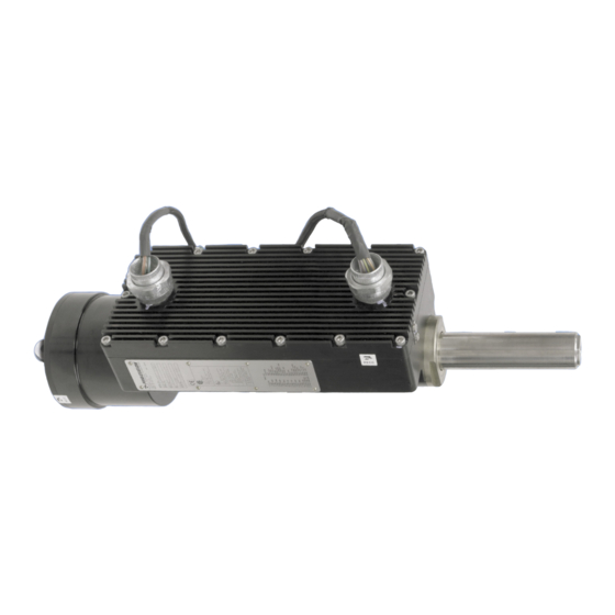
- Page 1 User Manual ACT2000 All-Electric Actuator SD-6008 Rev. 6 October 2008 PRECISION ENGINE CONTROLS CORPORATION...
- Page 2 This manual provides installation, maintenance, and operating instructions for the ACT2000 All-Electric Actuator. Every attempt has been made to provide sufficient information in this manual for the proper operation and preventive maintenance of the actuator. Read this manual in its entirety to fully understand the system.
-
Page 3: Table Of Contents
TABLE OF CONTENTS Purpose of This Guide ........................... iii Product Identification............................iii What the User Should Know ......................... iv Related Publications............................iv INSTALLING THE ACT2000 ........................1 1.1 Before Beginning............................. 1 1.2 General Specification Summary......................3 1.3 Mechanical Installation..........................4 1.4 Electrical Connections.......................... - Page 4 LIST OF FIGURES Figure 1-1. ACT2000-590P Dimensions ................7 Figure 1-2. ACT2000-200F Dimensions ................8 Figure 1-3. ACT2000-590P Pin-Mounting Provisions ............9 Figure 1-4. ACT2000-200F Flange-Mounting Provisions..........10 Figure 1-5: ACT2000 System Power Wiring Diagram............12 Figure 1-6. Typical Power Connection With Power Supply..........12 Figure 1-7. Typical Power Connection With Battery............12 Figure 1-8: ACT2000 System Signal Wiring Diagram ............16 Figure 1-9.
-
Page 5: Purpose Of This Guide
Purpose of This Guide This publication is designed to help the user install, operate, maintain and troubleshoot the ACT2000 All-Electric Actuator. Product Identification Most of the information in this manual is applicable to all generations of the product. Where unique information applies to a specific generation, one of the following symbols will be shown to indicate as such: Fourth generation (isolated RS-232) Actuator P/Ns: 50026XX-XXX or:... -
Page 6: What The User Should Know
What the User Should Know To install, operate, and troubleshoot the ACT2000, it is necessary for the user to have a fundamental understanding of: • Electronics concepts, such as voltage, current, and switches • Mechanical motion control concepts, such as inertia, torque, velocity, distance, force Related Publications •... -
Page 7: Installing The Act2000
1 INSTALLING THE ACT2000 1.1 Before Beginning Inspection The ACT2000 should be inspected immediately after unpacking. Check for dings or dents or any other obvious signs of damage. Remove the protective caps from the connectors and check for any bent pins or damage to the threads of the connectors. - Page 8 Electrical Noise Guidelines PECC has taken the following measures to reduce electrical noise with the ACT2000: • High-voltage wires are routed separately from low-level signals through the use of separate power and signal harnesses. An additional measure to reduce electrical noise is to: •...
-
Page 9: General Specification Summary
1.2 General Specification Summary PARAMETER VALUE Power Input Voltage Range 80-160 VDC; 120 VDC nominal Maximum Current 20 A Typical Transient Current +20A < 60ms; +10A < 600ms; -5A < 100ms Typical Continuous Current < 1A Inputs and Outputs Discrete Inputs ON Voltage: 12 –... -
Page 10: Mechanical Installation
Certifications North American Certifications CSA Class I, Div 1, Group B, C, D; T4 European Directive Compliance (CE Mark) EEx d, IIB+H ; T4 94/9/EC Potentially Explosive Atmospheres (ATEX) 08 ATEX 6108 X (replaces 02ATEX6050X) 98/37/EC Machinery Directive 89/336/EEC Electromagnetic Compatibility Directive (EMC) Materials Housing 6061-T6 Anodized Aluminum... - Page 11 Connecting the Clevis The ACT2000 features a clevis for securing the motor end of the actuator. A high-strength shoulder bolt (0.375” diameter) is recommended to fasten the actuator to a user-provided mount bracket. The clevis can be rotated to any orientation to support installation. Loosen the four retaining screws and rotate to the desired angle.
- Page 12 Note: It is important that user-supplied end attachments and connecting hardware align properly with the axis of the extension rod. Any misalignment will result in a side load on the extension rod (force applied perpendicular to the axis of extension rod) as it extends and retracts. Such a side load will reduce the efficiency of the ACT2000, requiring more electrical current to achieve a given amount of force or torque.
-
Page 13: Figure 1-1. Act2000-590P Dimensions
Figure 1-1. ACT2000-590P Dimensions INSTALLING THE ACT2000... -
Page 14: Figure 1-2. Act2000-200F Dimensions
Figure 1-2. ACT2000-200F Dimensions ACT2000 USER GUIDE... -
Page 15: Figure 1-3. Act2000-590P Pin-Mounting Provisions
Figure 1-3. ACT2000-590P Pin-Mounting Provisions INSTALLING THE ACT2000... -
Page 16: Figure 1-4. Act2000-200F Flange-Mounting Provisions
Figure 1-4. ACT2000-200F Flange-Mounting Provisions ACT2000 USER GUIDE... -
Page 17: Electrical Connections
1.4 Electrical Connections The ACT2000 is suitable for use in hazardous locations. See the General Specification Summary in Section 1.2 for certifications. Ensure compliance with the factory recommendations, and that wiring is in accordance with local requirements. WARNING: 94/9/EC (ATEX) Compliance – Special Conditions for Safe Use: Two special factory-sealed unions are mounted on the equipment to ensure the electrical connection to the network and to provide the feedback signal to the user. -
Page 18: Figure 1-5: Act2000 System Power Wiring Diagram
Figure 1-5: ACT2000 System Power Wiring Diagram ACT2000 120 VDC INPUT POWER SUPPLY PWR (RED) PWR AUX (WHT/RED) 120 VDC FUSE 50,000 µF PWR AUX RTN (WHT/GRN) PWR RTN (GRN) Figure 1-6. Typical Power Connection With Power Supply Figure 1-7. Typical Power Connection With Battery WARNING - Shock Hazard Connect both the 120 VDC power and auxiliary wires. -
Page 19: Table 1-2. Power Supply Requirements
Note: A battery system is recommended for highest reliability. Note: If a 120 VDC power supply is used rather than a battery, ensure an output capacitance of at least 50,000 µF, which can both sink and source electric current. See Power Supply Requirements (Table 1-2). -
Page 20: Table 1-3. Wire Size For Act2000 Power Harness
Therefore, it is not possible to correctly state a single capacitance value that should be placed on the bus. It may require no added bus capacitance or hundreds of thousands of microfarads of capacitance. A typical output capacitance value used for non-battery power systems is 50,000uF, but the actual value depends on the specific power system as discussed above. -
Page 21: Table 1-4. Wire List For Act2000 System Signal Harness
Signal Connections Signals are sent between the ACT2000 and the user’s controller through the integral 17-wire signal harness. The length of the signal harness is 90 inches. See Table 1-4 for the wire list for this harness. See Figure 1-8 for the system signal wiring diagram. -
Page 22: Figure 1-8: Act2000 System Signal Wiring Diagram
Engine ACT2000 Controller Demand DEMAND (BRN) Demand RTN DEMAND RTN (WHT/BRN) Shield GND Shield - No Connection RUN (VIO) Run RTN RUN RTN (WHT/VIO) Shield GND Shield - No Connection Reset RESET (GRY) Reset RTN RESET RTN (WHT/GRY) Shield GND Shield - No Connection Motor Current MTR CURRENT (BLU) -
Page 23: Figure 1-9. Typical Analog Input Connection
Analog Inputs The analog input, DEMAND, has a current range of 4 - 20 mA. It is electrically isolated up to 500 VAC from the enclosure, 120 VDC power, digital I/O, and serial interface. The analog interfaces are not isolated from each other. -
Page 24: Figure 1-12. Typical Discrete Output Alarm Connection
Discrete Outputs The discrete outputs are +24 VDC. They are electrically isolated up to 500 VAC. See Figure 1-12 for a typical discrete output alarm connection. CONTROLLER DISCRETE INPUT ACT2000 DISCRETE OUTPUT FAULT ALARM [ORN] OVERTEMP ALARM [BLK] FAULT RTN [WHT/ORN] OVERTEMP RTN [WHT/BLK]... - Page 25 WARNING Property Damage Hazard – The serial inputs are not electrically isolated . Failure to properly isolate the user serial interface could result in actuator or computer damage. Use separate conduits for power and signal wiring. Close proximity to power lines may cause signal interference.
-
Page 26: Table 1-6. Wire Size For Act2000 Signal Harness
Recommended Wiring for System Signals The recommended wiring is a 17-conductor shielded cable containing twisted-pair wires with individual shields. Use a wire size large enough to accommodate the installation and provide a maximum fifty (50) ohm loop resistance. See Table 1-6 for recommended wire sizes. DISTANCE TO USER’S RECOMMENDED CONTROLLER... -
Page 27: Understanding The Act2000
2 UNDERSTANDING THE ACT2000 2.1 System Description The ACT2000 is a closed-loop servo system containing motor control electronics (MCE) and a brushless-DC-motor-driven ball-screw actuator. The MCE contains analog-to-digital converters, a digital signal processor (DSP), application specific integrated circuits (ASIC) and power supplies. Figure 2-1 shows the system block diagram. - Page 28 also enables the ACT2000 and actuator to track the DEMAND signal. The actuator will move to the Stop Position if the RUN command is set to OFF or lost. RESET Command The RESET command is a user-provided discrete input to the ACT2000. This command causes the ACT2000 to reset all internal position indicators, reload all set-up parameters, and to then move the actuator through its initial homing sequence again.
-
Page 29: Figure 2-1. Act2000 Electronics System Block Diagram
Figure 2-1. ACT2000 Electronics System Block Diagram CH. 2: UNDERSTANDING THE ACT2000... - Page 30 Alarms The ACT2000 provides two two-wire alarm signals via the integral 17-wire signal harness. The discrete alarm outputs are solid-state switches which are normally closed. The user’s controller provides +24 VDC to complete the circuit. Refer to Figure 1-12 for typical connections. Refer to the General Specification Summary Table in Section 1.2 for alarm specification values.
-
Page 31: Mechanical Description
Note: The MCE analog and discrete signal interfaces are electrically isolated. The serial communication interface is optically isolated 2.3 Mechanical Description The ACT2000 consists of four main assemblies: • Main Housing Assembly • Brushless DC Motor Assembly • Resolver Assembly •... - Page 32 Resolver Assembly A brushless, non-contacting resolver is the primary ACT2000 feedback sensor. Resolver excitation is achieved via a sinusoidal signal from the MCE. The resolver provides two sinusoidal feedback signals back to the MCE. The resolver assembly includes a stator and rotor. See Figures 2-2 and 2-3.
- Page 33 nut to the main preloaded duplex thrust bearings. The thrust bearings transfer the loads to the main housing by the main bearing and shaft retaining nuts. A motor end bearing is provided for additional radial shaft stability. The resolver rotor, motor rotor, motor bearing, and spacers are all stacked on the ball screw shaft and retained by a single nut.
-
Page 34: Figure 2-2. Act2000-590P Cut-Away View
Figure 2-2. ACT2000-590P Cut-Away View ACT2000 USER GUIDE... -
Page 35: Figure 2-3 Act2000-200F Cut-Away View
Extension Shaft Rod End Bearing Anti-Rotation Guide Rigid Stop Linear Drive Main Housing Assembly Main Bearings Resolver Assembly Motor Rotor Brushless DC Motor Assembly Motor Stator Motor End Bearing Motor Cover Mounting Clevis Figure 2-3. ACT2000-200F Cut-Away View CH. 2: UNDERSTANDING THE ACT2000... -
Page 36: Identification Plate
2.4 Identification Plate A product identification plate is attached to the ACT2000 housing assembly. Figure 2-4 shows a typical identification plate. The identification plate lists model designation, product part number, revision and unit serial number. Hazardous area operation, certification and electrical wiring interface information is also provided. -
Page 37: Figure 2-5. Typical Refurbishment Plate
Figure 2-5. Typical Refurbishment Plate CH. 2: UNDERSTANDING THE ACT2000... - Page 38 NTENTIONALLY LANK ACT2000 USER GUIDE...
-
Page 39: Operating The Act2000
3 OPERATING THE ACT2000 3.1 Powering Up When 120 VDC is applied, the firmware program in the ACT2000 will clear all system registers, retrieve all necessary operating parameters from the electrically erasable programmable read only memory (EEPROM), and perform an internal status check. This will also happen after a RESET command has been received. -
Page 40: Holding Motor Current State
The ACT2000 will then slowly increase the motor current to the ACT2000 until the current level corresponding to the Maximum Homing Force has been applied. This Maximum Homing Force is also specified in the Set Up parameters and has a default value of 500 lbf. When the pre- determined motor current limit is reached, the ACT2000 defines this actuator position as Home. -
Page 41: Figure 3-1. Act2000 Basic Operation Flow Chart
Figure 3-1. ACT2000 Basic Operation Flow Chart CH. 3: OPERATING THE ACT2000... -
Page 42: Controlling Motion
3.5 Controlling Motion Once the Home position has been established, the DEMAND current determines subsequent positioning of the actuator within its span. The actuator will track the DEMAND signal as long as DEMAND ≥ 4.1 mA and RUN is ON, and will apply up to the maximum force to reach this DEMAND position. -
Page 43: Figure 3-2. Actuator Position Vs. Demand, Home As Mech. Stop In Actuator
The Span is tracked relative to the Home position. If Home position is based upon a mechanical stop in the user’s system, rather than the mechanical stop in the actuator, the actual amount of extension possible (or retraction) will be less than the default Span value of 5.9 inches. This can create a situation where the DEMAND signal correlates to a position beyond the design capacity of the actuator. -
Page 44: Figure 3-3. Dead Band Of Actuator, Position Vs. Demand Curve
Figure 3-3. Dead Band of Actuator, Position vs. DEMAND Curve Figure 3-4. Actuator Position vs. DEMAND, Home as a Mech. Stop in User’s System ACT2000 USER GUIDE... -
Page 45: Resetting The Actuator
3.6 Resetting the Actuator To reset the ACT2000, +24 VDC must be applied across the RESET wires for at least 0.5 seconds. The leading edge of the RESET command causes the ACT2000 to stop all other operations, but the actual resetting of the ACT2000 does not begin until RESET is returned to its OFF state. - Page 46 FAULT Alarm The configuration of faults assigned to the FAULT alarm is programmable in the most recent generation of the ACT2000 (factory-configurable only). See Table 3-1 for the default configuration of faults assigned to the FAULT alarm. See Table 3-3 for a list of fault conditions represented by the FAULT alarm in earlier generations of the ACT2000.
-
Page 47: Table 3-1. Default Configuration For Fault Alarm
Fault Type High Fault Persist Auto Output Alarm Alarm Enable Time Reset Driver Overcurrent 1000 lbf 10 Secs Tracking Error 3.33 % 10 Secs Position Demand 3.5 mA 20.5 mA 1 Sec RDC Failure +14 Volts 12.0 Volts 16.0 Volts 7.5 Secs –14 Volts –16.0 Volts... -
Page 48: Table 3-3. Fault Configuration For Fault Alarm
Fault Alarm Type Persist Time Fault Action Driver current > Max Force equivalent 10 Secs current, Fault. Driver Over Current Driver current > Max Force equivalent current, Fault. If persists for 1 Min., 1 Sec Shutdown Driver current > 18 Amps, Fault. If persists for 1 Min., Shutdown If in RUN state, not in home dead band 10 Secs... -
Page 49: Table 3-4. Fault Configuration For Overtemp Alarm
Fault Type Persist Time Fault Action Motor 10 Secs Motor temp > 130° C, Fault. . If fault exists and Motor temp > 135° C for 10 Secs, shutdown. 1 Sec Motor temp > 130° C, Fault . If fault exists and Motor temp >... -
Page 50: Changing Set-Up Parameters
3.8 Changing Set-Up Parameters The ACT2000 uses a number of variables to define its functionality. These variables are called Set-Up parameters and they are stored in the EEPROM in the ACT2000. Default values for these variables are loaded into the EEPROM at the PECC factory. The Set-Up parameters are reloaded into the system registers each time the ACT2000 is powered up or reset. -
Page 51: Table 3-5. Typical Act2000 Setup Parameters With Default Values
PARAMETER DESCRIPTION FACTORY SETTING Part Number Describes part number of actuator model Per Drawing Actuator Type Describes type of actuator Stand Alone Command Source Sets type of command signal Analog Home Controls the direction the actuator will Retract move, extending or retracting, to find the mechanical stop (HOME) Span Sets the maximum stroke length,... - Page 52 NTENTIONALLY LANK ACT2000 USER GUIDE...
-
Page 53: Maintaining The Act2000
4 MAINTAINING THE ACT2000 Under normal operation, the ACT2000 requires no formal maintenance program. Regularly scheduled inspections should be performed to check for: • any damage to wire insulation on integral 17-wire signal harness • any damage to wire insulation on integral 4-wire power harness •... - Page 54 NTENTIONALLY LANK ACT2000 USER GUIDE...
-
Page 55: Troubleshooting
5 TROUBLESHOOTING This section provides troubleshooting information for the ACT2000. You can isolate most electrical faults by using an external oscilloscope and digital voltmeter (DVM). The ACT2000 is comprised of highly reliable components and should not develop service problems under normal operating conditions. However, whoever is responsible for fault analysis should be thoroughly acquainted with physical and electrical configurations, Theory of Operation (Section 2), and Installation (Section 1). -
Page 56: Table 5-1. Initial Installation Troubleshooting Chart
Symptom Probable Causes Corrective Action Actuator Inoperative - Power Wires not connected Ensure RED and GREEN wires correctly connected to Actuator FAULT alarm No or low 120 VDC power Ensure 120 VDC Primary System Power at Actuator Actuator Inoperative - No RUN or position command Ensure VIOLET and WHITE/VIOLET wires correctly NO FAULT alarm... -
Page 57: Table 5-2. Act2000 In-Service Troubleshooting Chart
Symptom Probable Causes Corrective Action FAULT alarm Various Upload Fault File to identify source of fault OVER TEMP alarm Ambient temperature limit Allow actuator to cool and re-start exceeded Reduce ambient temperature Electronics or motor winding Check for jammed extension rod temperature out of range FAULT and OVERTEMP No 120 VDC Power... -
Page 58: Fault File
5.1 FAULT File The FAULT and OVERTEMP alarms are discrete outputs from the ACT2000. The FAULT and OVERTEMP alarm circuits are closed in the normal operating condition. If the ACT2000 detects a fault, the alarm circuit for that fault opens, and the user-provided controller should detect the open circuit. - Page 59 Watchdog expired The MCE watchdog timer continuously monitors the firmware program. Should the MCE firmware program stop functioning, or attempt to access an illegal address, the MCE signals a fault. This fault does not clear without RESET command. Resolver to Digital Converter (RDC) failure The MCE contains a resolver to digital converter chip (RDC) that provides position feedback information to the DSP.
- Page 60 NTENTIONALLY LANK ACT2000 USER GUIDE...
-
Page 61: Appendix A: Decommissioning & Disposal
APPENDIX A: DECOMMISSIONING & DISPOSAL This section contains recommended ACT2000 decommissioning and disposal practices. It is for permanent removal or replacement of the installed product, with no intentions of rework, overhaul, or to be used as spares. For removal follow proper lockout /tagout procedures and verify no live electrical circuits: •... - Page 62 NTENTIONALLY LANK ACT2000 USER GUIDE...
-
Page 63: Appendix B: Glossary
APPENDIX B: GLOSSARY Term Definition RUN Command A discrete 24 VDC signal that enables the ACT2000 extension rod to move. RESET Command A discrete 24 VDC signal that causes the ACT2000 internal program (firmware) to jump to the beginning. Controller A user-provided computer that executes commands to the ACT2000 and accepts analog and discrete feedback. - Page 64 NTENTIONALLY LANK ACT2000 USER GUIDE...