Table of Contents
Advertisement
Quick Links
Ecumaster Battery Isolator
Manual
Revision 0.7
1
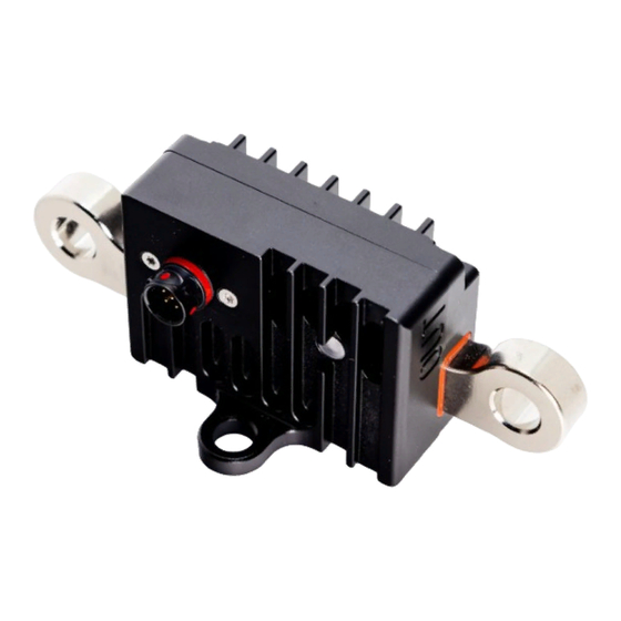
Device description
The Battery Isolator is a motorsport solid state device which can be used for FIA compliant battery
isolation and engine shutdown.
It is the most lightweight solution possible. The device is designed for harsh motorsport environment
and it weighs only 83g. The lack of mechanical components ensures long life and high reliability.
The device has a built-in alternator load dump protection without need of external components. This
means there is no risk of damage to expensive electronic equipment during emergency shutdown. It is
controlled with two external switches and can be shut down with a CAN-bus message. The message
can be sent from Ecumaster PMU16 unit in case of high impact or another event.
The device is configurable through CAN-bus and the Light Client software. It also transmits diagnostic
information which can be used by other equipment and is valuable during device setup and diagnosis.
State of the device is transmitted over CAN bus and also is indicated with multi-color led light.
It is fully protected for overheating and over-current.
Advertisement
Table of Contents

Summary of Contents for ECU Master Battery Isolator
- Page 1 Revision 0.7 Device description The Battery Isolator is a motorsport solid state device which can be used for FIA compliant battery isolation and engine shutdown. It is the most lightweight solution possible. The device is designed for harsh motorsport environment and it weighs only 83g.
-
Page 2: Specification
Specification • Weight: 83g • Dimensions: 50mm x 100mm x 38.5mm • Voltage range: 6V - 19V, 28V transient (12V automotive installations only) • Current capability: 300A continuous, peak up to 1000A • Current measurement resolution: 4A • Current measurement range: -1000A to 1000A •... -
Page 3: Installation
Installation • To avoid damage, it is advised to disconnect any electrical equipment during welding on car • Pay attention to correctly connect power terminals. Any attempt to crank the engine with reverse terminal connection will most likely damage the device. Polarity is clearly engraved on the case. - Page 4 The connector used for signals is Deutsch ASX 6 way. AWG 24 (0.2mm²) is maximum usable wire size. Crimping the contacts requires a special tool (M22520/2-01 with K1586 positioner) for motorsport or military size 24 terminals. If you're not equipped with such a tool or suitable gauge wire, please contact Ecumaster dealer sales department for a premade wiring loom.
-
Page 5: Operation Principles
Operation principles The device operation can be best explained with state machine diagram: • Relay: state of main relay, on or off • Output: state of ECU/PMU output: run or kill • Hold: state of internal power supply hold. When hold is off, power save switch will turn device off immediately. -
Page 6: Under Voltage Lock Out
• toggling red - EMERGENCY ENTRY PROC device countdown to Relay OFF mode Additional warnings (only in ON state): • yellow - overheat (temperature > 80°C) • short green flash - undervoltage (VBat < Battery Saver Threshold Voltage) • short red flash - overvoltage (VBat > 19V) •... - Page 7 Configuration The Battery Isolator is configured through the Ecumaster Light Client software. The device CAN-BUS must be accessed with a USBtoCAN interface or other compatible devices. For general Light Client usage refer to Light Client software manual.
- Page 8 Other message bytes are irrelevant. If the first byte is equal to 0x00 the function is not activated. For reliable operation only one device on CAN-BUS can transmit with a particular ID. To be able to be shut down by different devices, Battery Isolator will listen to four message IDs starting from Emerg. kill ID.
- Page 9 5.2 Channels • Voltage in - voltage on battery side • Voltage out - voltage on car side • Current load - current flowing through the relay. Positive values: battery to car, negative: car to battery (charging). Current load is not intended for precise current measurements but for general information on device load and charging.
-
Page 10: Troubleshooting
Troubleshooting Finding the reason why the isolator disconnected the battery is mainly based on reading device flags. Flags can be read via Light Client software. Possible options are listed below: • Device turned off and there are no flags active. ◦... - Page 11 ◦ Supply voltage exceeded the device specification. • battery saver kill - battery saver function was activated. ◦ Check battery saver setup. ◦ Check if alternator is charging the battery when the engine is running. • overvoltage kill - supply voltage exceeded the device specification. ◦...
-
Page 14: Revision History
Revision history Revision Date Changes 14.06.2019 Initial revision 17.07.2019 Battery saver and UVLO added 11.10.2019 Switch type and kill output hints added 28.11.2019 Drawing for lug and Radlok versions 12.12.2019 Text revised 16.06.2020 Troubleshooting, firmware 3.0...