
Related Manuals for CBS ArcSafe RRS-2-BE

Summary of Contents for CBS ArcSafe RRS-2-BE
- Page 1 CBS ArcSafe® RRS-2-BE (Remote Racking System) P.O. Box 550 Argyle, TX 76226 (940) 382-4411 www.CBS ArcSafe.com...
-
Page 2: Before You Begin
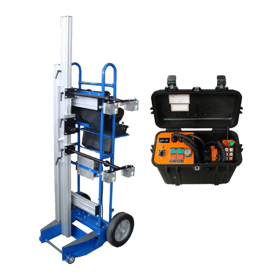
DANGER! *Ensure that switchgear is properly maintained and in good working order before using the RRS-2 on your switchgear. Contact your local group CBS service provider at www.gcbs.com to assist in proper care and maintenance for your switchgear. P.O. Box 550... - Page 3 1.0 Description The CBS ArcSafe® RRS-2-BE is a portable, highly configurable remote racking system designed to reposition circuit breakers that are equipped with non-rotary racking mechanisms. The primary goal for the design and operation of the RRS-2-BE remote racking system is to reposition circuit breakers with the operator positioned safely outside of the arc flash boundary.
-
Page 4: Preparation And Operation
3.1 Set up Training Included with your purchase of the RRS-2-BE is 4 hours of training from either a CBS ArcSafe® equipment representative or an approved CBS ArcSafe® outside representative. Please call CBS ArcSafe® at (940) 382-4411 to set up this FREE training seminar for your service personnel prior to ANY operations. - Page 5 4. If pneumatic tires are installed on the unit (optional), ensure the tires are inflated to their proper pressure. 5. Properly attach necessary tooling to the RRS-2-BE. 6. The CBS ArcSafe® RRS-2-BE is now ready for charging and setting up for operation.
- Page 6 3.3 Charging the RRS-2-BE The CBS ArcSafe® remote racking unit is equipped with batteries to enable operation when AC power is unavailable. Perform the following steps to charge and store the unit to prepare for future operation: 1. Rotate the power switch to the OFF position if not using the RRS-2-BE.
- Page 7 3.4 Setting the Actuator Limit Switches On the actuators used for pressing interlocks and for installing/removing breaker there are magnetic limit switches that help to control how far the actuators extend and retract. This allows the actuators to be set so that they only extend and retract to set limits and cannot over extend/retract themselves for operations where specific distances need to be traveled.
- Page 8 For selected models of circuit breakers, the RRS-2-BE will move slightly. This may include the RRS-2-BE slightly rocking or rolling forwards/backwards, however violent movements should not occur. If any movement seems concerning please contact your CBS ArcSafe® agent. 7. The RRS-2-BE is now ready for operation.
-
Page 9: Operation
4.0 Operation This section describes the steps necessary to install and remove the circuit breaker using the RRS-1. 4.1 Circuit Breaker Installation/Removal These are the following requirements and steps for circuit breaker installation using the RRS-1. 4.1.1 Requirements for Installation/Removal The following installation procedure assumes that the following prerequisites have been met: 1. - Page 10 DANGER! *Exiting the arc flash boundary may prevent the operator from observing the circuit breaker during repositioning, if this situation occurs we recommend acquiring the CBS ArcSafe® camera system in order to remotely view the repositioning. *Although the pendant station allows the operator to be away from the immediate arc flash boundary, personal protective equipment requirements must still be met at all times.
- Page 11 4.0 Operation This section describes the steps necessary to install and remove the circuit breaker using the RRS-2-BE. 4.1 Circuit Breaker Installation These are the following requirements and steps for circuit breaker installation using the RRS-2-BE. 4.1.1 Requirements for Installation The following installation procedure assumes that the following prerequisites have been met: 1.
- Page 12 DANGER! *Exiting the arc flash boundary may prevent the operator from observing the circuit breaker during repositioning, if this situation occurs we recommend acquiring the CBS ArcSafe® camera system in order to remotely view the repositioning. *Although the pendant station allows the operator to be away from the immediate arc flash boundary personal protective equipment requirements must still be met at all times.
-
Page 13: Maintenance
5.0 Maintenance 5.1 Introduction The CBS ArcSafe® RRS-2-BE is designed to require little maintenance; however, adopting a regular maintenance program will keep the RRS-2-BE in good condition allowing years of trouble-free service. 5.2 Prior to Use Before use examine the general condition of the unit. -
Page 14: Ordering Replacement Parts
6.0 Ordering Replacement Parts When ordering replacement parts please specify the serial number and MFD from the RRS-2-BE nameplate. From the RRS-2 nameplate: Nomenclature: RRS-2-BE Serial number MFD:... - Page 15 Remote Racking Unit RRS-2-BE Parts List ™ CBS ArcSafe Item Description Part Image Battery Charger Power Cable Male Power Connector Mounted Female Power Adapter...
- Page 16 Remote Racking Unit RRS-2-BE Parts List Cont. ™ CBS ArcSafe Item Description Part Image Power Switch PS-R6-C Radio Remote RSO Case w/ Components Standard Tires Pneumatic Tires...
- Page 17 Remote Racking Unit RRS-2-BE Parts List Cont. ™ CBS ArcSafe Item Description Part Image Front Wheel Magnet Brace...
-
Page 18: Appendix A: Radio Remote Pendant Station
The radio remote pendant station is designed specifically for the system that it came with. The radio remote will NOT work with any other CBS ArcSafe® Remote System, therefore please keep the radio remote with the system that it came with. Also to limit interference please ensure that the channel numbers of units purchased at different dates differ. - Page 19 2.0 Radio Remote Models PS-R6-C (Fig. D.1.2) The PS-R6-C radio remote has 4 control buttons that are designed to wirelessly control the included systems operation. In order to use the PS-R6-C the operator must ensure that the emergency-stop button is raised by rotating the button clockwise and turning the operating switch clockwise from the off position, past the on positions, to the start position and then releasing the switch letting it spring back to the on position.
- Page 20 P.O. Box 550 Argyle, TX 76226 Tel: 940-382-4411 Fax: 940-382-9435 Website: www.CBSArcSafe.com Email: info@CBSArcSafe.com DANGER! *Ensure that personnel using this equipment are adequately trained in the operation of the switchgear they are planning to work with; that they are correctly stationed outside the arc flash boundary;...
-
Page 21: Warranty Registration
*PLEASE TEAR OUT WARRANTY REGISTRATION – Products IMPORTANT: Complete and mail this warranty registration form as soon as possible. Date: RRS-2 RRS-2-BE CBS ArcSafe® Model (CIRCLE ONE): CBS ArcSafe® Serial Number: Company: Address 1: Address 2: City: State/Province: Zip/Postal Code:...
Need help?
Do you have a question about the ArcSafe RRS-2-BE and is the answer not in the manual?
Questions and answers