Table of Contents
Advertisement
Quick Links
Advertisement
Table of Contents

Summary of Contents for Durr Dental XR 04
- Page 1 INSTALLATION AND OPERATING INSTRUCTIONS X-RAY FILM PROCESSOR DÜRR XR 04...
-
Page 3: Table Of Contents
9.5 Mixing new chemicals ..... 11 1.5 Electrical Safety Notes ...... 5 1.6 Warnings and Symbols ..... 5 9.6 Assembling of the XR 04 ....12 10. Operation ..........12 2. Product information ........ 6 11. Replacing film transport cogs ..... 13 2.1 Use in accordance... -
Page 4: Important Information
• Any reprinting of the technical documentation, in whole or in part, is subject IMPORTANT to prior approval of Dürr Dental being given INFORMATION in writing. 1.3 General Safety Notes 1. NOTES This appliance has been designed and constructed by Dürr Dental so that correct 1.1 Test of conformity usage of the appliance is virtually free of any possible injury or danger. -
Page 5: Notes Concerning Medical Appliances
1.4 Notes concerning Medical 1.6 Warnings and Symbols Appliances In the Installation and Operating Instructions use is made of the following terms or symbols • This product is a technical medical to denote information of special importance: appliance and, as such, may only be operated by trained personnel, or persons Information and/or mandatory who, as a result of specialist knowledge, are... -
Page 6: Product Information
4. DELIVERY SCHEDULE 2.1 Use in accordance 4.1 Optional extras with regulations 1 X-ray film The Dürr XR 04 X-ray developing machine is Processor XR 04 ......1740-01 to be used exclusively for the automatic 1740-02 development of intra-oral X-ray films. -
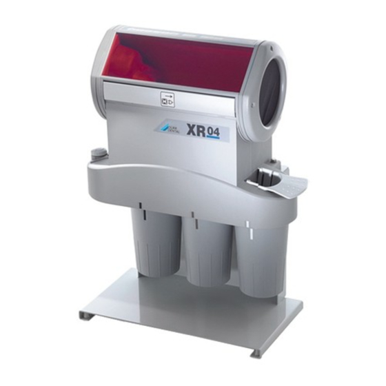
Page 7: Function Description
6. FUNCTION PRINCIPLE 7. FUNCTION DESCRIPTION E Developer bath Switch on main switch (2). F Fixer bath Heater for Developer/Fixer baths is started W Water bath (8 min/°C to 25°C bath temperature). 1 Processing time regulator Switch on regulator (1) for the film 2 Unit switch ON/OFF transport and set the processing time 3 Film transporter... -
Page 8: Installation
• Hang XR 04 on the screws, adjust as necessary, then tighten screws. Table mounting see pict. 2. Fit the upper part of the XR 04 onto the edge of the table and fasten it (11). Table installation see pict. 3. -
Page 9: Gebrauch
GEBRAUCH 9. CHANGING CHEMICALS AND WATER Before working on opened equipment, pull out the mains plug. • Change chemicals after approx. 200 films or after 3 weeks at the latest. • Change water twice a week. The information for changing the chemicals refer only when using "DÜRR Chemicals". -
Page 10: Cleaning Film Transport
9.2 Cleaning film transport • Lift the film transport (3, Fig. 5) upwards to remove and rinse with warm water at approx. 40°C. • If the film transport is very dirty it can be separated into two pieces and cleaned. Hereby : •... -
Page 11: Removing Heater
9.3 Removing heater Only necessary with table-top model, otherwise the Developer-/Fixer containers cannot be removed. Lift up Heater (4) and hang on frame. 9.4 Disposing of used chemicals • Remove by rotating the 3 containers Developer (E)/Fixer (F)/Water (W) and very carefully take off downwards. -
Page 12: Assembling Of The Xr 04
9.6 Assembling of the XR 04 • Replace heater (4) and film transporter (3), see pict. 5. • Replace daylight attachment (13). • Put the perforated collector (6) in the water container (6), see pict. 11 and right fold-in page. -
Page 13: Replacing Film Transport Cogs
11. REPLACING FILM TRANSPORT COGS • Remove the locking ring of the defective cog and pull the cog from the roller. • Align the transport arm (A) with marking (B), press new cog into position and secure with the locking ring. •... -
Page 14: Wiring Diagram
12. WIRING DIAGRAM 30 Mains 31 Heater DISPOSAL 32 Processing time regulator 33 Drive motor 34 PC board 13. DISPOSING OF APPLIANCE 35 Unit switch 36 Fuse 100 mA T The built-in electronic plate and components must be disposed of in the same way as electronic scrap metal.
Need help?
Do you have a question about the XR 04 and is the answer not in the manual?
Questions and answers