Table of Contents
Advertisement
Quick Links
Advertisement
Table of Contents

Summary of Contents for OsTech Laser Lab Source LDX Series
- Page 1 PRODUCT MANUAL LDX-976nm-45W contact@LaserLabSource.com contact@LaserLabSource.com 800.887.5065 800.887.5065 Laser Lab Source www.LaserLabSource.com 670 South Ferguson phone: 800-887-5065 Bozeman, MT 59718 a division of Research Lab Source Corporation...
-
Page 2: Overview
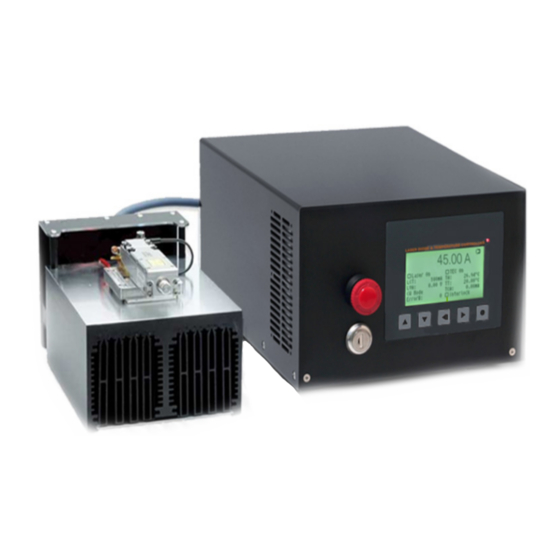
Overview The LDX-Series Laser Diode Sources are high quality fiber-coupled laser diode sources based on a robust and reliable laser diode and temperature controller architecture, with a focus on precision, reliability, and laser safety. All LDX systems include the controller, temperature controlled mount, and a carefully selected fiber- coupled laser diode from a top global manufacturer. - Page 3 TEC Controller Features • Thermosensor input for TCs standard 10 , PT100, PT1000 or others • Polynomial and Steinhart- art sensor model • P D temperature controller for TEC coolers • Voltage, current and temperature limits • Target temperature se uencer on re uest...
-
Page 4: Table Of Contents
Contents Overview Contents 1 Introduction 2 Technical parameters 2.1 General parameters ......8 2.2 Laser module . - Page 5 Contents 5.4.3 External analog modulation ....5.5 Pilot laser control ....... 6 Temperature controller and sensors 6.1 PID controller parameters .
-
Page 6: Introduction
O ur pe contact laserlabsource.com 800-8 OsTech, Berlin ermany Tel. 4 30 2 3040 contact ostech.de Please note that unauthorized opening of the device cancels the two year warranty. Don’t break the calibration seal! -
Page 7: Technical Parameters
2. Technical Parameters input voltage DS01: 24 V DC ± 10% DS11: 110–220 V AC ambient temperature 0 . . . 40 C humidity < 95% housing size width◊height◊depth (depth without connectors) o44 housing 105 mm 44 mm 160 mm (4.1 in 1.7 in 6.3 in) -
Page 8: Security Breakdown Conditions
accuracy ±2 % laser diode voltage min. 1.2 V max. 3 | 6 | 9 | 12 | 15 | 18 | 24 | 48 V current noise 1 % . . . 0.01 % of I internal pulse mode pulse width range µs . -
Page 9: Peltier Module
Model Specific TEC Controller peltier current range ±1.5 | ± 2.5 | ± 4 | ± 8 | ± 10 | ± 12 | ± 16 A accuracy /4000 ±I peltier voltage max. 4 | 8 | 14 | 18 | 24 | 48 V temperature controller range ≠25 C . -
Page 10: Keypad And Display Menus
3. Keypad and Display Menus For OEM-Type Models, this section does not apply. • increases the digit under the cursor DOWN • decreases the digit under the cursor LEFT • moves to the previous input field, unsaved changes are discarded RIGHT •... -
Page 11: Laser Menu
switch the laser on and o , can only be changed if the device has Laser On no separate laser switch laser current target laser voltage actual laser current bias (for modulation) modulation mode CW Mode, ... Mod. switch the TEC controller on and o TEC On target temperature TT, LTT, CTT... -
Page 12: Tec Menu
laser current limit compliance voltage ( laser voltage actual laser current bias (for modulation) limit for average laser current (for modulation) LCLM laser temperature maximum, laser stops above this temperature error number (0 = no error) Error# no modulation CW Mode external analog modulation LMAX external digital modulation... -
Page 13: Device Menu
TEC voltage actual TEC controller is automatically activated when the temperature is TC Auto On whithin limits restores the default settings for the TEC controller Restore Def. upper temperature limit lower temperature limit set the PID coe cents (see figure 3.3b) PID parameters select one of some predefined temperature sensor settings (see... - Page 14 default fan voltage Reset all settings in the device to their default values. Restore Default Settings Show type, serial number and software version of the device. Service Figure 3.4: Device menu.
-
Page 15: Hardware Setup Preparations
4. Hardware Set-Up Preparation These steps must be followed: • Make sure that the power supply is disconnected from main • Use an approved personal grounding bracelet or other means for ESD protection during the assembly of the laser or other electronics. •... -
Page 16: Laser Control
5. Laser Diode Current First the laser current limit and the laser compliance voltage be configured. To adjust the laser current limit using the display: • go to the by pressing Laser Menu • go to the input field by pressing to adjust the laser current limit •... -
Page 17: Ramp On Laser Switching
Laser : 0 . . . 34000 ms LZTR (default: 300 ms) LZTR LZTR Figure 5.1: Laser current on-off ramp in CW mode. The ramp is active at any change of laser current. When using the RS232 interface the command LR may be used to switch the laser on. -
Page 18: Gate Option
5.3 Gate option Before turning the laser on you must connect the photo sensor between the PDC (cathode) and the GND (anode) pins at the laser connector. After this you should test whether the sensor . For this run the laser and check with the command (laser photo current actual). -
Page 19: Internal Digital Modulation Mode
laser laser current target – : 100 . . . 2 µs : 200 . . . 2 µs + 100 µs laser bias current – Figure 5.2: continuous pulse mode menu show the mean values not the peak values. These measured values may differ from the adjusted ones caused by the low speed of the AD converter. -
Page 20: External Digital Modulation
as in continuous pulse mode 0 . . . 64000 LMDIC continuous pulse mode LMDIC single pulse mode LMDIC = 2 . . . 64000 n-pulses mode LMDIC LMDIC Figure 5.3: single pulse mode, n-pulses mode the number of pulses will be generated. Afterwards, the driver enters the OFF state automatically. -
Page 21: Pilot Laser Control
5.5 Pilot Laser Control These laser diode drivers support an internal pilot laser. One pin on the laser peltier connector is reserved for this purpose. n ON state a voltage between 4.0 and .0 V is applied. The maximum output current is 1 0 mA. n OFF state the output is near 0 V level. -
Page 22: Temperature Controller And Sensors
6. TEC Controller and Temperature Sensors As some models may have more than one TEC controller, the temperature sensor or TEC controller is selected by a prefix, in this chapter written as x. So, x has to be replaced by a digit (or letter) to select the temperature sensor or TEC. The first temperature sensor or TEC corresponds to , the second to , the third to... -
Page 23: Temperature Sensor
3-wire option for PT100 R = 4, 27 k SSUP SINP DRIVER PLUG CABLE SENSOR Figure 6.1: schematic for connecting a temperature sensor 0.2. . . 5 TCCK 5. . . 50 TCCN 0.2. . . 2 TCCV f you don t now anything about the TEC circuit, you may set TCC 0.2, 2 and TCCV 0.1. - Page 24 6.2 Temperature sensor The default coefficients c and c of this polynomial correspond to an NTC ◦ with 10 kW at 25 C which is a wide spread standard. You may adjust these coefficients to a different sensor by the commands x .
- Page 25 For tolerances of real sensors you may need to calibrate the setup point of your sensor by adding the difference between the real temperature and the shown temperature to the absolute part x TSC0 If you need assistance in connecting your sensors or you want to assemble any other sensor to the driver we would be pleased to assist you in finding the appropriate coefficients.
-
Page 26: Remote Control
7. Remote Control All models may be controlled over a serial interface. The transfer parameters of the serial interface are fixed to 00 baud 8 1. 7.1 Standard Mode In standard mode you can send commands and parameters to the device in text forma t and the device answers in the same way. -
Page 27: Binary Mode
To return to standard mode this bit has to be cleared: sent command: clear bit 0x08 of mode variable GMC8 7.4 Software you may download software to interact with OsTech http://www.ostech.de devices. • the terminal program OSTERM • LabVIEW™ VIs, including a runtime version... -
Page 28: Error Codes
8. Error Codes When an error occurs, the driver generates an error code. The error code can bedetermined by the GE command. Furthermore, the error is shown on the display. A list of error codes and their causes follows: error code cause no error interlock open... -
Page 29: Command Reference
9. Command References 9.1 Laser Commands type default unit description bool laser stop/run float laser temperature maximum bool gate option 9.1.1 Laser Current Commands type default unit description float + 5% + 5% current limit float current target float — no parameter — actual current float base or bias current... -
Page 30: Laser Modulation Commands ( )
9.1.4 Laser Modulation ommands ( type default unit description bool internal digital modulation LMDI bool external digital modulation LMDX bool external analog modulation LMAX float 1000000 1000 pulse width µs float + 100 600000000 2000 pulse period µs word 65534 number of pulses LMDIC word... -
Page 31: Temperature Sensor Commands
As the fi rst temperature sensor o r TEC is usually used for a laser and the second for a crystal, a deprecated option for selecting them is the use of the letters respectively. In new firmware v ersions t he s ensor c ommands a re a lso available w ith p refix n instead o f x where n corresponds to the number o f the temperature sensor. -
Page 32: Status Command
type default unit description float default fan voltage bool external control stop/run float — no parameter — device temperature (head) word — no parameter — software version word — no parameter — serial number 9.3.1 Status Command type default unit description word —...
Need help?
Do you have a question about the Laser Lab Source LDX Series and is the answer not in the manual?
Questions and answers