
Subscribe to Our Youtube Channel
Related Manuals for Power One VSN-MGR-RES Series

Summary of Contents for Power One VSN-MGR-RES Series
- Page 1 AURORA LOGGER RESIDENTIAL AND COMMERCIAL INSTALLATION GUIDE VSN-MGR-RES SERIES VSN-MGR-CMML SERIES BCM.00099.0AL REV AB...
- Page 2 DISCLAIMER The information, specifications, configurations and other technical information regarding the products referenced herein are subject to change without notice. All the statements, technical information and recommendations contained herein are believed to be accurate and reliable but Power-One Corporation makes no representations or warranties with respect to accuracy or completeness of the contents of this Manual.
- Page 3 Power-One Corporation (“Seller”) hereby warrants that the product for which this User WARRANTY Guide is written (the “Equipment”) will comply in all material respects with Seller’s published specification for a period of two (2) years from the date of shipment. For any material breach of the foregoing warranty, Seller’s sole and exclusive obligation and buyer’s sole and exclusive remedy for breach of the foregoing warranty shall be, at Seller’s option, to either repair, replace or issue credit for the nonconforming product,...
-
Page 4: Table Of Contents
System Overview ____________________________________________________________ 5 Installation _________________________________________________________________ 6 Preparation ___________________________________________________________________ 6 Aurora Logger Installation________________________________________________________ 7 Power One Inverter Address Configuration _________________________________________ 10 Commissioning _____________________________________________________________ 10 Connect to the Internet _________________________________________________________ 10 Run the Setup Tool ____________________________________________________________ 11 Configure for Inverter Devices ___________________________________________________ 12 3.3.1... -
Page 5: System Overview
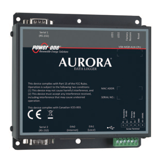
1 System Overview The Aurora Logger is a lightweight solution for remote data acquisition, which enables PV system owners to benefit from advanced energy reports. The Aurora Logger collects and analyzes energy generation data from all connected Power-One inverters and optional weather station for commercial loggers. -
Page 6: Installation
The information in this document applies to all Aurora Logger Models for Residential and Commercial. This guide provides instructions for installing the Aurora Logger hardware to work directly with a Power-One inverter(s) and for setting up Aurora Vision Management system for remote data access. The Aurora Logger consists of a Data Logger/Gateway and AC Power Supply adaptor. -
Page 7: Aurora Logger Installation
It is also useful to know if you need to perform Asset Registration or final End-to-End Data Checks after physical installation is complete. If so, you will need a User ID/password to log in to Aurora Vision, and additionally you will need Administrator privileges to access the Aurora ADMIN tool. - Page 8 Connect other end of shielded twisted-pair wire to the Secondary RS-485 terminals on the Aurora Logger. Use the table below and the figure on the next page to make the proper connections. See Section 4 for more information on wiring the optional weather station to the Aurora Logger.
- Page 9 Termination Switch PVI-x.x Outdoor PVI-xxxx Indoor Series Series (U.S.) PVI-x.x Outdoor Series The Power Adapter comes packaged with your Aurora Logger with an Output Plug attached. Cut the Output Plug using standard wire cutter and strip the two conductors for connecting them to the Screw Terminal of the Aurora Logger. Attach the conductor with white label, which is a positive +12 VDC cable, to Port 6 of the Aurora Logger Screw Terminal.
-
Page 10: Power One Inverter Address Configuration
Power-One inverters use a proprietary RS-485 communication interface, and therefore 2.3 Power One Inverter Address Configuration must be daisy-chained to the Secondary RS-485 terminal connectors. For system with address. Refer to the inverter manual(s) for instructions on how to set inverter addresses multiple inverters, each inverter must be manually assigned a different RS-485 and exact inverter connection points. -
Page 11: Run The Setup Tool
If no activity is seen on the LEDs, double-check all connections. Power-One recommends a wired Ethernet Internet connection because it is more reliable and requires less setup. If it is necessary to connect to a wireless network, a wireless network bridge with an Ethernet port is required. -
Page 12: Configure For Inverter Devices
Select the tabs across the top to perform configuration operations and select one of the ports in the Devices list to set up devices. Verify all the icons for the Aurora Logger in the status area to the right are green. It may take some time for all the icons to turn green. -
Page 13: Set A Static Ip Address
Setting a Static IP is only necessary if required by your network. In almost all cases you can 3.3.1 Set a Static IP Address skip this section. 1. Obtain Static IP address information for the site. 2. Select the Network tab. Set the Type (Network Connection Type) field to Static. The page will allow you to type in the following information: IP address •... -
Page 14: Verify Internet Connectivity
3.4 Verify Internet Connectivity 1. Verify that the Ethernet cable is connected between Eth0 and your network. 2. The Aurora Logger acts as a router. From your laptop connected to Eth1, verify your internet connectivity by opening up an Internet browser window and connecting to an Internet address, such as www.yahoo.com. -
Page 15: Aurora Easy View Access For End User
The installer must supply the user with the Easy View URL so they access Aurora Easy View 3.7 Aurora Easy View Access for End User and monitor their system. To find the URL for a specific user site within Aurora Vision, follow these steps: 1. - Page 16 4. A page displays to configure the Easy View display. Scroll down to the Published View section. The URL to provide to the customer is in the Latest version field.
-
Page 17: Adding A Weather Station
Weather stations are wired to the Primary RS-485 port on the Aurora Logger. 4 Adding a Weather Station 1. Connect shielded twisted-pair wire to the RS-485 terminals on the weather/environmental station. Use a RS-485 data wire with one twisted pair, one ground conductor, and a shield with drain wire (Belden#3106A or equivalent). -
Page 18: Configuration For A Weather Station Device
4. Connect other end of shielded twisted-pair wire to the power and ground terminals (terminals 6 and 5) on the Aurora Logger. Wire the weather station to the Aurora Logger as shown in the figure below. To Network via Aurora Logger Switch or Router Use Twisted Pair Wire Positive (+) - Page 19 1. Go to the Home tab. Click on the Pencil icon across from Devices. The following screen appears: 2. The screen shows the current configuration settings for each port. Select the Plus (+) button on the Primary RS-485 bar to add a device. A window appears to enter device settings.
- Page 20 6. Click the Add button. 7. The device will be added to the Devices page, listed under the Primary RS-485 port. 8. Press the Save icon at the top to commit changes. 9. After making changes, you are reutrned to the Devices page with the status indicators, as shown below.
-
Page 21: Troubleshooting
5 Troubleshooting 5.1 Troubleshooting Guide a. Verify the Aurora Logger is connected to power and the Aurora Logger POWER LED = GREEN. 1) Issue: Aurora Vision does not show recent information from the monitoring system. b. Verify that the Aurora Logger has a network link, by checking that the LED on the Aurora Logger is green. -
Page 22: How To Contact Power-One Technical Support
d. Check to make sure the RS-485 communication wires are properly connected. Make sure the data conductors are not swapped. Measure the DC Voltage across D+ and D- at both the monitoring enclosure and at the data terminals of the remote device. If the measurement is 0 DC you have a short in the data wires. - Page 23 a. Two RS-232 serial ports terminated with 9 pin MALE D-SUB connectors. Support baud Serial Connection rates up to 230kbps. b. Two RS-485 serial ports supported on a single screw terminal block. Supports baud rates up to 115200 bps. c. Up to 5 Power-One single-phase inverters are supported by the Aurora Logger Residential. d.
-
Page 24: Remote Power Wire Sizing
The Aurora Logger is using the following IP Network Services: IP Network Services Directi Service/Port Protocol Description ssh/22 For remote firmware upgrades, the Aurora Logger utilizes encrypted SSH Remote Login Protocol. To enable upgrades over the Internet, this port has to be opened in any firewall and forwarded to this device. - Page 25 Power-One 740 Calle Plano Camarillo, California, 93012 United States Customer Support Phone: 877-261-1374 Customer Support E-mail: www.power-one.com vision.service@power-one.com © 2012 Power-One Corporation. Power-One is a registered trademark and Aurora Vision is a trademark of Power-One Corporation. All rights reserved. All other brand or product names are trademarks or registered trademarks of their respective holders.
Need help?
Do you have a question about the VSN-MGR-RES Series and is the answer not in the manual?
Questions and answers