Table of Contents
Advertisement
Quick Links
Advertisement
Table of Contents

Summary of Contents for NuDAQ ACL-7225B
- Page 1 ® NuDAQ ACL-7225B 16 Relay & 16 Isolated DI Card User’s Guide...
- Page 3 Trademarks NuDAQ is a registered trademark of ADLINK Technology Inc. Other product names mentioned herein are used for identification purposes only and may be trademarks and/or registered trademarks of...
-
Page 6: Table Of Contents
Contents Chapter 1 Introduction ............. 1 Features................1 Applications..............2 Specifications ..............2 Software Supporting............3 Chapter 2 Installation ..............4 What You Have ............... 4 Unpacking............... 5 PCB Layout..............6 Jumper and DIP Switch Description ....... 7 Base Address Setting ............. 7 Input Signal Type Selection .......... - Page 8 How to Use This Guide This manual is designed to help you use the ACL-7225. It describes how to operate the ACL-7225 card to meet your application requirements. It is divided into three chapters: lChapter 1, "Introduction," gives an overview of the product features, applications, and specifications.
-
Page 10: Chapter 1 Introduction
Introduction The ACL-7225 - 16-CH Relay Actuator and Isolated D/I card is a compact size ISA Bus card for industrial applications. This card provides 16 relay actuators and 16 opto-isolated digital input channels. You can use 16 on-board relays to control power switches or ON/OFF control devices. -
Page 11: Applications
1.2 Applications Industrial ON/OFF control Energy management External high power relay driving, signal switching Laboratory automation Industrial automation Switch contact status sensing, limit switch monitoring 1.3 Specifications Relay Outputs Relay Type: Double-Pole-Double-Throw (DPDT) Number of Relays: 16 ♣R0~R4 and R8~R12 are in Form C ♣R5~R7 and R13~R15 are in Form A Contact Rating: 120VAC/ 0.5A or 24VDC 1A Contact Type: Bifurcated... -
Page 12: Software Supporting
I/O Connectors: One 37-pin Female D-type connector, one 40- pin h eader, an accessory is provided to converter the 40-pin header into 37-pin D-type connector Compatible Bus: IBM PC-AT Bus Operating Temperature: 0° C ~ 50°C Storage Temperature: -20° C ~ 80°C Humidity: 5 ~ 90%, non-condensing Dimension: 177mm(L) X 122mm(W) 1.4 Software Supporting... -
Page 13: Chapter 2 Installation
Installation This chapter describes how to install the ACL-7225. The following procedures show the installation procedures: 1. Check what you have 2. Check the PCB and check the location of jumper and switch 3. Setup the jumpers according to the operation theorem 4. -
Page 14: Unpacking
2.2 Unpacking Your ACL-7225 card contains sensitive electronic components that can be easily damaged by static electricity. The card should be done on a grounded anti-static mat. The operator should be wearing an anti-static wristband, grounded at the same point as the anti-static mat. -
Page 15: Pcb Layout
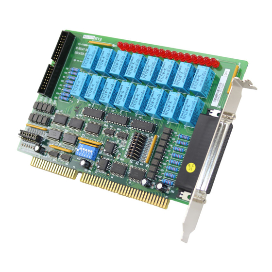
2.3 PCB Layout Figure 2.1 6 • Installation... -
Page 16: Jumper And Dip Switch Description
2.4 Jumper and DIP Switch Description You can change the ACL-7225's input signals and base address by setting jumpers and DIP switches on the card. The card's jumpers and switches are preset at the factory. Under normal circumstances, you should not need to change the jumper settings. A jumper switch is closed (sometimes referred to as shorted) with the plastic cap inserted over two pins of the jumper. - Page 17 I/O Port Address (Hex) 200-207 208-20F 2F8-2FF (*) 300-308 308-30F 3F8-3FF (*) : default setting ON = 0 ; OFF = 1. A9, ..., A3 are corresponding to PC Bus address lines A9 is fixed as 1, and A2, A1 and A0 are fixed by 0 with hardware How to Define a Base Address for the ACL-7225 ? The DIP1 to DIP7 in the switch SW1 are one to one corresponding to the PC bus address line A3 to A8.
-
Page 18: Input Signal Type Selection
2.4 Input Signal Type Selection The ACL-7225's input signal can be selected either AC input or DC input signal. There are 16 jumpers (JP1...JP8 and JP9...JP16) associated with each digital input channel for configuring the channel as AC or DC input. The digital i n put channels and their corresponding jumpers is shown in the following Table 2.3. -
Page 19: Connector Pin Assignments
2.3 Connector Pin Assignments The ACL-7225 card comes equipped with two I/O connectors CON1 and CON2. The CON1 is an on-board 40-pin connector, and CON2 is a 37 pin D-type connector accessible from the rear panel of the card, and . The pin assignment of these connectors is described by Figure 2.4 and Figure 2.5, respectively. - Page 20 NO10 CM10 NC10 NO11 NC11 CM11 NO12 CM12 NC12 NO13 CM13 NO14 CM14 NO15 CM15 DIB8 DIA8 DIB9 DIA9 DIB10 DIA10 DIB11 DIA11 DIB12 DIB13 DIA12 DIA13 DIB14 DIA14 DIB15 DIA15 40-pin Ribbon NO10 CM10 NC10 NO11 CM11 NC11 NO12 CM12 NC12 NO13...
-
Page 21: Dos Software Library Installation
2.4 DOS Software Library Installation This section describes the DOS software library, which is free supplied. The function prototypes and some useful constants are defined in the header files in LIB directory. The DOS library software includes a utility program, C language library, and some demonstration programs, which can help you reduce the programming work. -
Page 22: Chapter 3 Registers Format
Registers Format The registers format of ACL-7225 is described in this chapter. 3.1 Registers Map The ACL-7225 requires 8 consecutive addresses (only 4 are used) in the PC I/O address space. The following table (Table 3.1) shows the location of each register and driver relative to the base address, and its description. -
Page 23: Isolated Input Registers
The readback capability is also support in the ACL-7225, i.e. you can read back each relay's status through the relay output registers. The relationships between the bit of relay output register and its corresponding relays are shown as below. Data Format: Realy Output Register: (Base + 0) Realy Output Register: (Base + 1) RO15 RO14 RO13 RO12 RO11 RO10... -
Page 24: Relay Output
3.4 Relay Output The ACL-7225 contains two types of relays: Form C and Form A. The relay R0 ~ R4 and R9 ~ R12 are form C relays, and R5 ~ R7 and R13 ~ R15 are form A type. The difference between these two types of relay are : 1. -
Page 25: Programming Examples
3.6 Programming Examples The ACL-7225's registers can be accessed through direct I/O instructions, such as inport and outport instructions in Borland C/C++ language. You can write (outport) control word to relay output register to turn the relay's ON/OFF. Also, you can read (inport) back the signal of relay status or isolated input signals. -
Page 26: Appendix A. Realy Contact Protection Circuits
Appendix A. Realy Contact Protection Circuits The contacts are the most important elements of relay constructions, Contact performance conspicuously influenced by contact material, and voltage and current values applied to the contacts. Another important issue is contact protection, a right contact protection circuit can suppress the counter emf to a low level. - Page 27 C : 0.5 to 1 µF per 1A contact current Value vary depending on the properties of the capacity C acts to suppress the discharge the moment the contacts open. Resistor R acts to limit the current when the power is turned on the next time. Test to confirm.
- Page 28 4. Varistor Circuit This circuit is also suitable for both AC & DC applications. Using the stable voltage characteristics of the varistor, this circuit prevents excessively high voltages from being applied across the contacts. This circuit also slightly delays the release time. Effective when connected to both contacts of the power supply voltage is 24 or 48V and the voltage across the load is 100 to 200 V.
-
Page 29: Product Warranty/Service
Product Warranty/Service Seller warrants that equipment furnished will be free form defects in material and workmanship for a period of one year from the confirmed date of purchase of the original buyer and that upon written notice of any such defect, Seller will, at its option, repair or replace the defective item under the terms of this warranty, subject to the provisions and specific exclusions listed herein.
Need help?
Do you have a question about the ACL-7225B and is the answer not in the manual?
Questions and answers