Advertisement
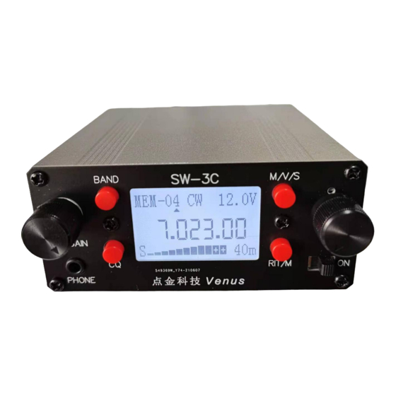
SW-3C 3 band CW QRP Transceiver
manual
Specifications
Size:
100*44*103mm (not including protrusions such as knobs)
Weight:
about 250 grams.
Input voltage: 10-14VDC.
Current consumption:
When receiving, turn on the backlight about 80mA, turn off the backlight about 65mA.
When transmitting, about 0.7-0.8A (when voltage is 12V)
Frequency Range:
Receiving 5-8MHz, 8-11MHz, 11-16MHz (the peak receiving sensitivity is only in the 40m, 30m, 20m amateur
band)
Transmit:
7.0-7.2MHz, 10.1-10.15MHz, 14.0-14.35MHz.
Filter:
CW, SSB, automatically switch according to the mode, CW filter bandwidth is about 400Hz, SSB is
about 2KHz.
RIT/XIT RIT adjustment range: -9KHz to +9KHz, XIT adjustment range: -30KHz to +30KHz.
RF Output power: about 5W (when the power supply voltage is 12V)
Side tone:
600Hz
Automatic keyer: The speed of the built-in automatic keyer is adjustable.
Stored frequency memories: Each band has 8 stored frequency memories, the frequency and mode can be stored
by the user.
Receive mode: CW, CWR, USB, LSB. CW signal can also be transmitted in SSB working mode, so as to realize the
cross communication of CW/SSB.
AGC Simple audio AGC, S meter shows the relative strength of the signal.
Advertisement
Table of Contents

Related Manuals for Venus SW-3C

Summary of Contents for Venus SW-3C
- Page 1 SW-3C 3 band CW QRP Transceiver manual Specifications Size: 100*44*103mm (not including protrusions such as knobs) Weight: about 250 grams. Input voltage: 10-14VDC. Current consumption: When receiving, turn on the backlight about 80mA, turn off the backlight about 65mA. When transmitting, about 0.7-0.8A (when voltage is 12V)
- Page 2 Connections External power supply Any 10-14V DC voltage or battery can be connected through the external power jack. The power jack has a polarity protection circuit to prevent damage to the machine due to reverse power connection. Headset Connect stereo headphones to the headphone jack (PHONE), impedance 8-32 ohms. Antenna Any resonant antenna can be directly connected to the antenna input (ANT) with a BNC connector.
- Page 3 Power switch and Gain control The power switch is in the lower left corner of the panel, turn it to the right to turn on the power. The AF GAIN knob on the left side of the radio panel is the audio gain control knob, turn it clockwise to the end to maximize the gain.
- Page 4 Press the M/V/S button for more than 2 seconds to store the current frequency and mode in the current storage unit. The word Sav-** will be displayed in the upper left corner of the LCD screen. Everytime the radio powered on,last saved memory of band, frequency and mode will recall.
- Page 5 Transmit The allowed transmit frequencies are: 7.0-7.2MHz, 10.1-10.15MHz, 14.0-14.35MHz. When sending a message in these frequency ranges, the display will show TX, the S meter under the LCD will change to display the transmit power P. There are 3 scales on the transmit power scale except for the 0 scale. The approximate power of the first scale is 1W, the second scale (slim one) is about 3W, and the third scale is about 5W (because the radio detects the RF voltage output to the antenna port, so the displayed power is only accurate when the SWR is close to 1:1 ).
- Page 6 At this time, use a frequency meter to detect the frequency of the TEST point on the PCB board (between IC4 and IC5), turn the knob on the right side of the radio panel to adjust the frequency until the frequency meter displays 7.000.00MHz, press the M/V/S button for about 2 seconds Just exit. Wuxi Venus Information Technology co., Ltd 2021-06...
Need help?
Do you have a question about the SW-3C and is the answer not in the manual?
Questions and answers