Table of Contents
Advertisement
Quick Links
Advertisement
Table of Contents

Related Manuals for Grant UFLEX EDGE


Summary of Contents for Grant UFLEX EDGE
- Page 1 UFLEX EDGE...
-
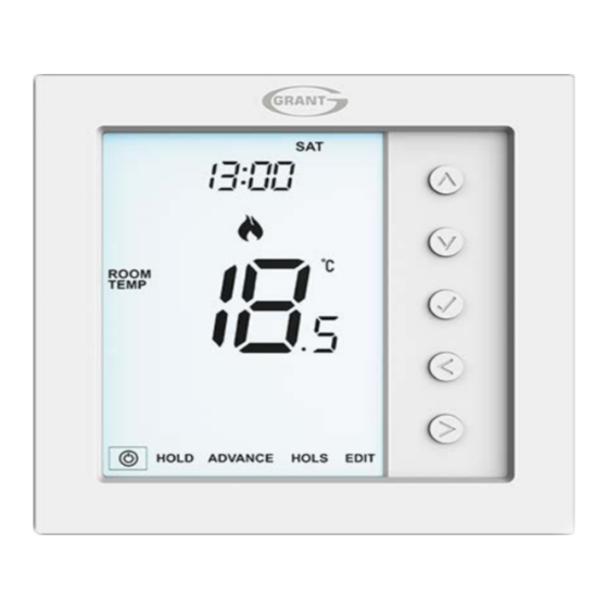
Page 2: Product Image
Model: UFLEX EDGE UFLEX Series... -
Page 3: Table Of Contents
Table of Contents Product Image Locking/Unlocking the UFLEX EDGE Table of Contents Holiday What is a Programmable Optional Settings Explained 26-27 Room Thermostat? Optional Settings - Feature Table Installation Procedure Adjusting the Optional Settings Mode Select Fail Safe/Modbus Recalibrating the UFLEX EDGE... -
Page 4: What Is A Programmable
What is a Programmable Room Thermostat? A programmable room thermostat is both a programmer and a room thermostat. A programmer allows you to set “On” and “O ” periods to suit your own lifestyle. A room thermostat works by sensing the air temperature, switching on the heating when the air temperature falls below the thermostat setting, and switching it o once this set temperature has been reached. - Page 5 Programmable room thermostats need a free ow of air to sense the temperature, so they must not be covered by curtains or blocked by furniture. Nearby electric res, televisions, wall or table lamps may also prevent the thermostat from working properly. UFLEX EDGE...
-
Page 6: Installation Procedure
You can then carefully separate the front half from the back plate. Step 2 Place the UFLEX EDGE LCD front plate somewhere safe. Terminate the thermostat as shown in the diagrams on page 32-35 of this booklet. Step 3 Screw the thermostat back plate securely into the back box. - Page 7 UFLEX EDGE...
-
Page 8: Mode Select
Mode Select This device can either be used as a thermostat or a time clock. Thermostat mode is the default setting. To change between thermostat & time clock modes, follow these steps. then press and hold the • Use the ‘Left/Right’ arrow keys to highlight button for 3 seconds .................... -
Page 9: Mode 1 - Thermostat
Mode 1 - Thermostat UFLEX EDGE... - Page 10 2 3 4 UFLEX Series...
-
Page 11: Lcd Display
15. Temperature – Displays the current sensor temperature. 16. Temperature Format - Degrees Celsius or Fahrenheit. 17. Window Icon - Displays when Window/Door Switch is triggered. 18. Time/Day/Month/Year - Displays when setting the Clock/Calender or a Holiday Period. UFLEX EDGE... -
Page 12: Power On/Off
Power On/O The heating is indicated ON when the ame icon is displayed. When the Flame Icon is absent, there is no requirement for heating to achieve the set temperature but the thermostat remains active. To turn the thermostat o completely, scroll to the Power Icon and hold the key for approximately 3 seconds until the display goes blank ...... -
Page 13: Setting The Time & Date
‘Minutes’ .... Repeat the previous two steps to set the date (‘Day, Month & Year’). Display will go blank once completed. • Press the ‘Down’ arrow key followed by to return to the main display ........................UFLEX EDGE... -
Page 14: Temperature Display
Temperature Display This thermostat can be con gured for di erent sensor options such as built sensor, oor sensor or both. The display will clearly indicate which sensor is being used by showing either ‘ROOM TEMP’ or ‘FLOOR TEMP’ to the left the actual value. Room Temperature Floor Temperature When the thermostat is set to use both the air &... -
Page 15: Pairing Accessories
Wireless Air Sensor. Door/Window - Wireless Contact Sensor* (Not available in Time Clock mode). You can pair a total of 16 accessories to a single UFLEX EDGE thermostat. Wireless Air Sensor Once a remote sensor is added, the thermostat will automatically display an average temperature between the ‘Wireless Air Sensor’... - Page 16 The thermostat will now start a 99 second countdown. During this time multiple sensors can be added. Number of accessories connected. Countdown time • On the ‘Air Sensor & Window/Door Contact’ , press and hold the pairing button for 5 seconds. The LED will glow red to indicate pairing status Window/Door Wireless Contact Sensor Wireless Air Sensor Pair/Reset...
-
Page 17: View Accessories
If the ULFEX EDGE thermostat loses connection with an accessory, the display will show “--”. A battery warning symbol will be appear when an accessory reports low power. When this happens change the Lithium Cell CR2302 3V battery as soon as possible. UFLEX EDGE... -
Page 18: Removing Accessories
Pair/Reset button button At this point the ‘Sensor/Contact’ will notify the UFLEX EDGE thermostat that it has left, and will automatically be removed from the ‘Accessory Menu’ . On the UFLEX EDGE thermostat • Follow the steps on page 16 to enter the accessory menu. -
Page 19: Edit Comfort Levels
Edit Comfort Levels The UFLEX EDGE o ers three program mode options; Weekday/Weekend, 7 Day and 24 Hour programming. There is also the option to use this device as a manual thermostat. The thermostat is supplied with comfort levels already factory programmed, but these can be changed easily. - Page 20 • Use the ‘Up/Down’ keys to set the ‘Hours’ ............. • Press to con rm ......................... • Use the ‘Up/Down’ keys to set the ‘Minutes’ ............• Press to con rm ......................... • Use the ‘Up/Down’ keys to set the temperature ..........•...
-
Page 21: Temperature Control
........Until next programmed ‘Comfort Level’ time. Set Temperature Note: This new temperature is maintained only until the next programmed comfort level. At this time, the thermostat will revert back to the programmed levels. UFLEX EDGE... -
Page 22: Temperature Hold
Temperature Hold The temperature hold function allows you to manually override the current operating program and set a di erent temperature for a desired period. • Use the ‘Left/Right’ keys to scroll to ‘Hold’ and press ........• Repeatedly tap the ‘Up/Down’ keys to set the desired ‘Hold’ time (Hours) then press .................... -
Page 23: Advance
Press to exit ......... • To change the ‘SET’ temperature during ‘Advance’ , use the ‘Up/Down’ keys followed by to con rm ........To cancel ‘Advance’ • Use the ‘Left/Right’ keys to highlight ‘Advance’ then press twice ..UFLEX EDGE... -
Page 24: Frost Protection
The frost icon will toggle ON/OFF each time is pressed ............In this mode, the UFLEX EDGE will display the frost icon and will only turn the heating ‘ON’ should the room temperature drop below the set frost temperature. If the heating is turned ‘ON’... -
Page 25: Locking/Unlocking The Uflex Edge
Locking the UFLEX EDGE The UFLEX EDGE has a keypad lock facility. To activate the lock follow these steps. • Use the ‘Left/Right’ keys to scroll to Hold & press for 7 seconds ..The display will show 0000. At this point enter a four digit pin number. -
Page 26: Holiday
The UFLEX EDGE will maintain this temperature for the duration of the holiday and will then automatically return to the program mode on your return. -
Page 27: Optional Settings Explained
Sensor Selection: On this thermostat, you can select which sensor should be used. You can select between air temperature only, oor temperature, or both. When you enable both sensors, the oor sensor is used as a oor limiting sensor and is designed to prevent the oor from overheating. UFLEX EDGE... - Page 28 Floor Temp Limit: When the Floor Sensor has been enabled in feature 07, you can set a oor limiting temperature between 20-45°C, this protects the oor from overheating. (27°C is the default). Note: ‘Air Sensor Only’ MUST NOT be used to control electric under oor heating. Floor Sensor or Both should be used.
-
Page 29: Optional Settings - Feature Table
00 = 5/2 01 = 7 Day 02 = 24 Hour 03 = None programmable (DST) Daylight Saving 00 = Disabled (Default) 01 = Enabled Communications ID 01-32 (Modbus) 00 = Disabled Program Type 00 = 4 Comfort Levels (Default) 01 = 6 Comfort Levels UFLEX EDGE... -
Page 30: Adjusting The Optional Settings
Adjusting the Optional Settings then press and hold the • Use the ‘Left/Right’ arrow keys to highlight button for 3 seconds ..................... The display will go blank showing only ‘Setup’ and ‘Clock’ • Press the ‘Up’ key followed by twice to access main feature menu .. -
Page 31: Fail Safe/Modbus
• All Modbus connections should be daisy chained rather than wired in a star formation. • If the UFLEX EDGE is the last Modbus device on the end of the chain, move the toggle switch on the back of the fascia to the ‘On’ position. -
Page 32: Recalibrating The Uflex Edge
‘ON’ ..........Error Codes The UFLEX EDGE will display an error code if there is a fault with the temperature sensor, these error codes are explained below. E0 = The internal sensor has developed a fault. -
Page 33: Wiring Diagrams
Wiring Diagram - UFLEX EDGE Switch Live Output Model: UFLEX EDGE MODBUS INTERFACE 230VAC Floor Sensor A2 A1 230V SUPPLY IN LIVE NEUTRAL SWITCHED LIVE TO BOILER This product must only be installed by a quali ed electrician and comply with local installation regulations. - Page 34 Wiring Diagram - UFLEX EDGE Volt Free Output (Thermostat & Time Clock Modes) Model: UFLEX EDGE MODBUS INTERFACE 230VAC Floor Sensor A2 A1 230V SUPPLY IN VOLT FREE TO BOILER LIVE LS & LR ARE NORMALLY THE ROOM THERMOSTAT CONNECTIONS...
- Page 35 Wiring Diagram - UFLEX EDGE to Valve Model: UFLEX EDGE MODBUS INTERFACE 230VAC Floor Sensor A2 A1 TO CONNECT BOILER CONSULT BOILER MANUFACTURERS DIAGRAM LIVE 230V SUPPLY IN NEUTRAL TO BOILER NEUTRAL LS & LR ARE NORMALLY THE HEATING VALVE...
- Page 36 Wiring Diagram - UFLEX EDGE Switch Live to UFLEX UH8 Model: UFLEX EDGE 230VAC MODBUS INTERFACE Floor Sensor A2 A1 FLOOR PROBE UFLEX UH8 This product must only be installed by a quali ed electrician and comply with local installation regulations.
-
Page 37: Mode 2 - Time Clock
Mode 2 - Time Clock UFLEX EDGE... - Page 38 UFLEX Series...
-
Page 39: Lcd Display
2. Holiday – Displayed when the time clock is in holiday mode. 3. Clock - Time displayed in 24 hour format. 4. Advanced Until - Displayed when the UFLEX EDGE is advanced to the next programmed level. 5. Hold Left - Displayed when a timer override is active, the remaining time will be shown. -
Page 40: Setting The Switching Times
Setting the Switching Times To program the switching times, follow these steps. • Use the ‘Left/Right’ keys to scroll to ‘EDIT’ ................• Press to con rm selection ....................• Use the ‘Up/Down’ keys to select the day/period to program ......•... -
Page 41: Timer Advance
• Use the ‘Up/Down’ keys to set output On or OFF then press to con rm ..Hold Left and the remaining time will now be displayed. To cancel Timer Override • With ‘HOLD’ highlighted, press twice ..............UFLEX EDGE... -
Page 42: Optional Settings Explained
Optional Settings Explained Programming Mode: The following program modes are available; 5/2 Day Programming - 4 On/O switching times for the weekdays and 4 On/O switching times for the weekend. 7 Day Programming - 4 individual On/O switching times for each day. 24 Hours - 4 On/O switching times over a 24 hour period. -
Page 43: Adjusting The Optional Settings
• Use the ‘Left/Right’ keys to change feature setting .......... • When all required changes have been made press to con rm settings and return to the blank display ..................once to power on ....• Use the ‘Down’ key to select then press UFLEX EDGE... -
Page 44: Replacing The Battery
Replacing the Battery In most cases the 3 volt lithium battery does not need replacing if the thermostat has a continual power supply. Its sole purpose is to ensure correct time keeping during a power loss to the thermostat. To remove the battery use a small at head screw driver or ngertip to push back the brass retaining bracket. - Page 45 Notes ........................................................................................................................................................................................................................................................................................................................................................................................................................................................UFLEX EDGE...
- Page 46 Notes ........................................................................................................................................................................................................................................................................................................................................................................................................................................................UFLEX Series...
- Page 47 Notes ........................................................................................................................................................................................................................................................................................................................................................................................................................................................UFLEX EDGE...
- Page 48 Want More Information? ROI: Call 0579120089 or visit www.grantengineering.ie NI: Call 0800 2794796 or visit www.grantni.com G.B. (England, Scotland and Wales): Call 01380 736920 or visit www.grantuk.com Rev. 1.0...
Need help?
Do you have a question about the UFLEX EDGE and is the answer not in the manual?
Questions and answers