Table of Contents
Advertisement
Quick Links
CBS Products Ltd, Pillings Road, Oakham, Rutland, LE15 6QF, UK
Tel: +44(0) 1572 723 665
Fax: +44(0) 1572 756 009
E-mail:
sales@cbsproducts.com
Website:
www.cbsproducts.com
OPERATING MANUAL
C–1800 (ACCELAIR 2)
FIBRE BLOWING MACHINE
Copyright 2016 by CBS Products Limited
All rights reserved. No part of this publication may be copied, reproduced or
transmitted in any form whatsoever without the written permission of CBS
Products Ltd.
Advertisement
Table of Contents

Subscribe to Our Youtube Channel
Related Manuals for CBS C–1800

Summary of Contents for CBS C–1800
- Page 1 OPERATING MANUAL C–1800 (ACCELAIR 2) FIBRE BLOWING MACHINE Copyright 2016 by CBS Products Limited All rights reserved. No part of this publication may be copied, reproduced or transmitted in any form whatsoever without the written permission of CBS Products Ltd.
- Page 2 REVISION HISTORY: Rev.no Date Details Author 30.05.14 Original issue C.Swallow Power supply input voltages changed, 19.06.14 C.Swallow 1.6mm blowing plate was buckle plate Reverse instructions added, photos 5-2-15 C.Swallow updated 4-3-15 Air seal replacement instructions added C.Swallow Duplicate replacement air seal section 25-8-15 C.Swallow removed...
-
Page 3: Table Of Contents
Contents 1. SAFETY INSTRUCTIONS ..............5 2. CRITICAL POINTS THAT DRAMATICALLY AFFECT THE OPERATION OF THE BLOWN FIBRE BLOWING MACHINE .... 9 3. GENERAL DESCRIPTION ..............11 4. SPECIFICATION ................. 12 5. MAJOR ELEMENTS ................13 6. OPERATING PROCEDURE .............. 15 7. - Page 4 14. CHANGING THE DISPLAY LANGUAGE ........35 15. TROUBLESHOOTING GUIDE ............36 16. MONTHLY SERVICE – CHECK LIST ..........38 17. CHANGEABLE PARTS AND ACCESSORIES ........ 39 Page 4 of 41...
-
Page 5: Safety Instructions
SAFETY INSTRUCTIONS THIS EQUIPMENT SHOULD BE USED ONLY BY PERSONNEL WHO HAVE BEEN GIVEN THE APPROPRIATE TRAINING AND WHO ARE COMPETENT TO USE IT. THESE INSTRUCTIONS ARE TO BE MADE AVAILABLE TO OPERATORS OF THIS EQUIPMENT AT ALL TIMES, FAILURE TO OBSERVE THESE SAFETY INSTRUCTIONS COULD RESULT IN SERIOUS PERSONAL INJURY AND/OR PROPERTY DAMAGE. - Page 6 Never leave the machine unattended whilst in use. Consider the use of safety barriers, especially when used in public places, observe all statutory requirements for working environments. Beware of pinch points involved with rotating components, Beware of hot surfaces, machine uses compressed air. ...
- Page 7 FAILURE TO DO SO MAY RESULT IN PERSONAL INJURY OR DAMAGE TO THE BLOWN FIBRE. If a mains power supply is used and the connecting plug on the mains power lead to the generator / (or supply) is unsuitable and requires replacement, the new plug must be correctly connected observing the colour codes as below.
- Page 8 GENERAL PNEUMATIC SAFETY INSTRUCTIONS The CBS Blown Fibre Blowing Machine is a pneumatic device, using pressurised air to project fibre at high velocities. Please observe the following precautions when operating the Blowing Machine:- Compressed air can cause flying debris. This could cause personal injury.
-
Page 9: Critical Points That Dramatically Affect The Operation Of The Blown Fibre Blowing Machine
The compressed air moisture content needs to be carefully controlled, it should be dry enough to prevent moisture forming in the tubes yet not so dry to cause a static build up – CBS Products recommend the use of an air dryer with a bypass. - Page 10 DISCLAIMER CBS Products Ltd takes care in the design of its products to ensure that the cable is protected during installation. Due to the variety and different methods of fibre manufacture the responsibility of checking the fibre compatibility with the equipment lies with the operator. Therefore, CBS products cannot accept liability for any damage to the fibre.
-
Page 11: General Description
The machine only requires a single 24V D.C. electrical supply and compressed air to operate. CBS Products Ltd has designed a range of accessories aimed at providing the complete solution to blown fibre installation. Page 11 of 41... -
Page 12: Specification
SPECIFICATION Fibre Compatibility: Up to 1.6mm with buckle, up to 3mm without buckle Blowing Speed: Manual control to 50 metres per minute Compatible Tubes: Any size from 3mm to 10mm Automation: In buckle mode machine is self-regulating Air Supply: 15 Bar max working pressure complete with suitable air conditioning (drying) Electrical Supply: Universal mains power supply (supplied as... -
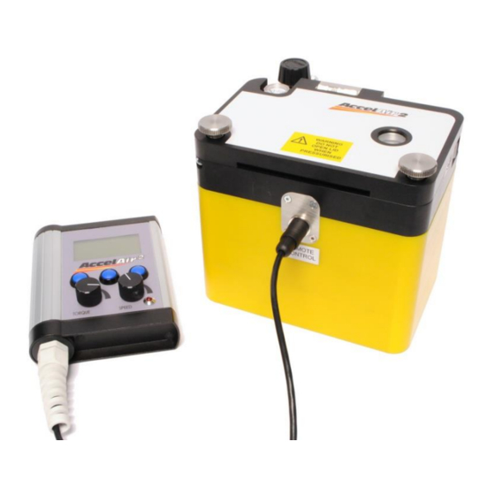
Page 13: Major Elements
MAJOR ELEMENTS Blowing Plates Lid Locking Screws Pressure Gauge Sight Glass Wheel Tube Clamp Opening Handle Buckle Shuttle Infeed guide Drive Wheels Remote Connection LCD Display Buckle Indicator LED User Interface Page 13 of 41... - Page 14 Air Control Valve Lid Locking Screws Connection Connection CARRY CASE LAYOUT Power Tools / Accessories Wires Universal Remote Accelair 2 Mains Power Unit Machine Supply Page 14 of 41...
-
Page 15: Operating Procedure
AUTHORISED TO USE IT AND HAVE READ AND UNDERSTOOD THIS MANUAL CBS PRODUCTS LTD. CANNOT BE HELD RESPONSIBLE FOR MISUSE OF THIS EQUIPMENT. SETTING UP THE TUBE AND FIBRE To begin an installation first we must connect the tube and fit the fibre through the machine. - Page 16 Place the tube seal over the end of the tube and insert into the machine as shown with the tube flush up to the air inlet and the seal in the groove. Do not allow the tube to protrude into the air inlet as this will restrict air flow and performance.
- Page 17 NEVER OPEN THE LID OF THE MACHINE WHEN IT IS UNDER PRESSURE, SERIOUS INJURY MAY OCCUR DUE TO ITEMS EXPELLED AT HIGH VELOCITY. CBS Products recommend the use of a stop end at the end of the tube route to arrest the fibre at the end of the installation.
- Page 18 FIBRE INSTALLATION To begin an installation first power up the machine. With the remote unit already plugged in, insert the power cable into the rear of the machine. The LCD display on the remote unit should now power up with the following display: Select the option by pressing the relevant blue button under either...
- Page 19 The two dials control the torque setting and speed. The maximum speed of the machine is 50m/min. Adjustment of the torque setting is only relevant when installing fibre with buckle functionality disabled. This message will be displayed if the buckle mode is selected and the shuttle cannot be detected.
- Page 20 To check the buckle function and to allow a viewing point for the fibre CBS Products suggest a small length of tube with a clear connector be used in the machine first. Moving the fibre in and out should be possible;...
- Page 21 As the fibre is moved into the machine the screen will first display ‘warning’ and then when more fibre is fed through it will display ‘active’. Eventually it will display ‘error’; do not worry, this simply means the buckle shuttle has moved beyond the sensing range.
- Page 22 The speed and torque settings can be adjusted at any time by moving the dials either clockwise or anti-clockwise. The machine will slow instantly but will accelerate slowly previously described. After 30-50m of fibre has been installed it will be necessary, as resistance increases, to introduce airflow down the tube.
- Page 23 The installation of fibre should now be semi-automatic. If the buckle function is not in use then the machine will come to a stop when there is a blockage; the fibre will be undamaged as there will not be enough torque to break it. Once the machine has come to a stop, press ‘stop’...
- Page 24 It is advisable to finish the current job to ensure the next installation begins with the distance reset to zero. To do this select ‘OPTIONS’ from the installation screen followed by ‘Finish Job’. You will be asked to confirm this selection. Reverse Mode It is possible to reverse the Accelair 2 machine to remove any fibre previously installed.
- Page 25 Imperial Units The Accelair 2 machine can display metric or imperial measurement formats as well as European and American date formats. To set your machine to the desired units navigate to the settings screen. Scroll down to ‘Units of Measure’ and press ‘SELECT’. You can now scroll down and individually change the displayed units and date format by pressing ‘CHANGE’.
-
Page 26: Maintenance
MAINTENANCE The CBS Blown Fibre Blowing Machine has been designed to give reliable, trouble free service over long periods. The machine requires no sophisticated maintenance procedures; simple common sense checks and precautions are all that are needed. The main source of breakdown and/or malfunction of a machine being used outdoors is contamination by the elements, this contamination may be introduced into the machine in a number of different ways. -
Page 27: Procedure For Changing The Blowing Plates
PROCEDURE FOR CHANGING THE BLOWING PLATES The C-1800 Accelair 2 uses two types of blowing plates. One type is for use in conjunction with the buckle functionality and one without. The buckle plates use 4 off M3 cap screws each to retain them into the machine; the non- buckle plates use 3 off each. - Page 28 Store the removed plates in the bag provided and in the designated area of the carry case to avoid loss or damage. The above figure shows the air seal beneath the lower blowing plate. This seal should sit proud of the surface; if it has become flattened or damaged replace to maintain a good air seal and blowing performance.
-
Page 29: Procedure For Replacing The Blowing Plate Air Seal
Apply a small amount of adhesive at critical points around the groove (near bends etc). CBS Products Ltd recommends the use of 3M Scotch IT IS IMPERATIVE THAT YOU DO NOT Weld 847 for this purpose. - Page 30 Using a sharp knife and taking care not to damage the plates, slice a section of the seal away at the fibre entry point sufficient to allow the fibre free movement through the plate. Page 30 of 41...
-
Page 31: Procedure For Replacing Tube Clamp Inserts And Infeed Guides
10. PROCEDURE FOR REPLACING TUBE CLAMP INSERTS AND INFEED GUIDES Various tube clamp inserts and infeed guides are available for the C-1800 Accelair 2 to allow the use of different tube and fibre sizes. Both the tube clamp inserts and infeed guides are retained using 2 off M3 cap screws each and require the use of the 2.5mm allen key. -
Page 32: Procedure For Replacing Tyres
11. PROCEDURE FOR REPLACING TYRES The C-1800 Accelair 2 uses a replaceable silicone tyre to provide grip to install the blown fibre. Two sizes are available; one for smaller fibres and one for larger fibres. When installing a different fibre or through wear it will be necessary to replace these tyres. -
Page 33: Checking The Odometer
12. CHECKING THE ODOMETER The C-1800 Accelair 2 has an odometer to indicate the total distance the machine has installed during its service life. This can be accessed via the ‘System Information’ page from the main menu. Also displayed will be the ID numbers for the Accelair 2 machine and the remote unit. -
Page 34: Determining Maximum Torque Setting
13. DETERMINING MAXIMUM TORQUE SETTING When preforming an installation of a larger or stiffer fibre it may be necessary to use a non-buckle or ‘straight’ set of blowing plates. To ensure the integrity of the fibre at all times during the installation it is crucial a test is performed. -
Page 35: Changing The Display Language
14. CHANGING THE DISPLAY LANGUAGE The Accelair 2 machine can display in several languages – English, French, German, Spanish, Portuguese and Italian. To set your machine to the desired language navigate to the settings screen. Scroll down to ‘Language’ and press ‘SELECT’ and scroll through to select the desired language. -
Page 36: Troubleshooting Guide
15. TROUBLESHOOTING GUIDE Air loss from the Accelair 2 machine is greater than normal: o Ensure the correct changeable parts are fitted for the fibre and tube being used. o Check air seal beneath the lower blowing plate; replace if necessary. - Page 37 o Ensure a buckle leaf is fitted in buckle plates and that it moves freely in the groove. No drive/Drive wheels slipping: o Smaller tyres may be needed for improved grip – follow section 11 for details on changing tyres. o Tyres may be excessively worn –...
-
Page 38: Monthly Service - Check List
16. MONTHLY SERVICE – CHECK LIST This section is included in the manual for your convenience, there follows a list of suggested checks, it is recommended that these checks be carried out on a regular basis, depending on use. Monthly checks are convenient; a few minutes can be set aside on the same day of each month to complete these simple checks. -
Page 39: Changeable Parts And Accessories
Pack of Silicone Tyres (Up to 2mm fibre, 5 pairs) C-1800-T1 Pack of Silicone Tyres (2.1 – 3.0mm fibre, 5 pairs) C-1800-T2 Only common blowing plate and tube clamp sizes shown, please contact CBS Products sales team for additional sizes. SPARES Description... - Page 40 Other sizes of clear tube connector are available. Air flow meter can be used to check route integrity. Please contact the CBS Products sales office to order or enquire about parts not listed; always quoting the machine type and serial number.
- Page 41 Mr Andrew Sibun Position: Technical Manager Done at: Oakham, United Kingdom Document Ref/No. 4th June 2014 C-1800/CE The documentation for the machinery is available from: Name: CBS Products Ltd Address: Pillings Road, Oakham, Rutland, LE15 6QF Page 41 of 41...
Need help?
Do you have a question about the C–1800 and is the answer not in the manual?
Questions and answers