
Summary of Contents for Pulsar SandAlert Lite Second Edition
- Page 1 SandAlert Lite 2 CHANNEL PORTABLE SAND MONITORING SYSTEM OPERATING HANDBOOK SandAlert Lite Second Edition...
- Page 2 Pulsar Process Measurement Limited guarantee for a period of 12 months from the date of delivery that it will either exchange or repair any part of the Sand Monitoring System returned to Pulsar Process Measurement Limited if it is found to be defective in material or workmanship, subject to the defect not being due to fair wear and tear, misuse, modification or alteration, accident, misapplication or negligence.
-
Page 3: Table Of Contents
CONTENTS WHAT’S NEW? 1 INTRODUCTION 2 STRESS WAVE SENSING - THE TECHNOLOGY 3 SYSTEM OVERVIEW 3.1 Acoustic Sensor 3.2 SandAlert Lite 3.3 Power Supplies 3.4 Signal Processing Technique 4 INSTALLATION 4.1 Sensor Positioning 4.2 How to fit the pipe clamp to the pipe 4.3 Electrical Installation of SandAlert Lite 5 QUICK GUIDE TO INSTALLATION 5.1 Attach the sensor to the pipe... -
Page 4: What's New
What’s New? This is the first edition of the manual and therefore nothing is new, but in future editions new features will be indicated with a symbol throughout this handbook. SandAlert Lite 2 Edition Page... -
Page 5: Introduction
As a result, the Pulsar Process Measurement acoustic sensor can readily provide a non-intrusive method of detecting the impacts and abrasions of solid particles in the fluid flow, and is immune to interference from airborne noise and structural vibration. -
Page 6: Acoustic Sensor
Figure 1 Schematic Diagram of the SandAlert Lite Acoustic Sensor There are two transducers suitable for sand monitoring: Pulsarguard 2011G This sensor is the ‘G’ version, suitable for use with the inbuilt galvanic barriers of the SandAlert Lite. The sensor transducer is housed in a robust cast Type 316 stainless steel enclosure. There are two sensor variants available, the Pulsarguard 2011 sensor which is approved to EEx ia IIC T6, or EEx ia IIC T5 for T up to 92 ºC. - Page 7 PulsarGuard 2001 The sensor is a Pulsar Process Measurement intrinsically safe acoustic sensor. The sensor is housed in a robust cast Type 316 stainless steel enclosure. The Sensor is called the PulsarGuard 2001 and...
-
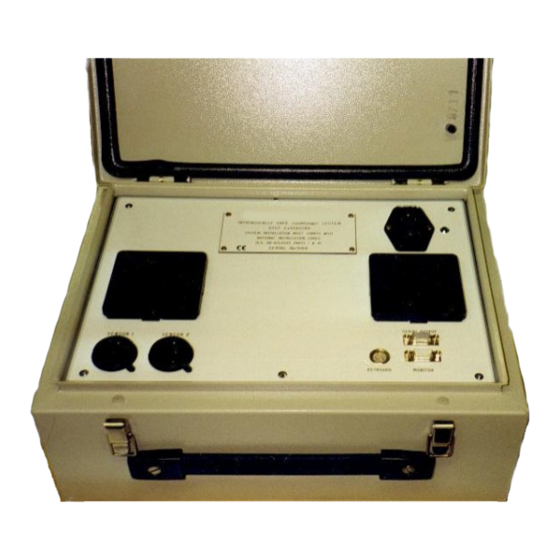
Page 8: Sandalert Lite
SandAlert Lite The SandAlert Lite is housed in a rugged painted steel case. The electrical interface between hazardous and non-hazardous area is provided by an internal galvanically isolated safety barrier. The SandAlert Lite uses a compact processor board with 2 MB RAM, and a hard disk drive on which the software is installed. - Page 9 The electrical signal or sensor output is converted into a digital signal by the ADC in the SandAlert Lite. The sensor output is then processed to provide a sand impact rate (SIR) in impacts per second (IPS). To be counted as a sand impact the peak amplitude of the pulse must exceed the low threshold but not exceed the high threshold.
-
Page 10: Installation
Threshold Threshold c - High Flow, No Sand d - High Flow, With Sand The SandAlert Lite unit eliminates the flow noise by placing a threshold automatically just above the flow related noise signal, and if the signal goes higher than this then it is due to solid impacts, which can be seen in b and d as short duration, high energy spikes, as compared with the flow related noise that is longer duration, and of lower energy. -
Page 11: How To Fit The Pipe Clamp To The Pipe
obtained if the sensor is positioned on or just after a bend (within two pipe diameters of the bend), or fixed restriction to the flow. See Figure 4. Figure 4 Sensor Positioning Do not position the sensor in close proximity to a choke, or other variable restriction, since changes in the choke position may affect the SIR readings. -
Page 12: Electrical Installation Of Sandalert Lite
IMPORTANT: The sensor cannot be damaged by overtightening since the clamp is in contact with the metal tab part of the sensor and not the electronics which are contained within the dome part of the housing. It is recommended that the clamp is tightened to at least 40 lbf/ft, and the locking nut is tightened. -
Page 13: Quick Guide To Installation
Connect the sensor to the cable using the in-line cable plugs and sockets, the plug and socket will only mate in the correct way, tighten the collet to secure the connection. Connect the short interconnection cable from the cable reel to the SandAlert Lite. Refer to the system diagram (Figure 1) to ensure that all the electrical connections have been made correctly. - Page 14 Start ‘Terminal’ To use ‘Terminal’, start Windows (by typing “Win” from the Windows directory), and locate the ‘Terminal’ within the Windows ‘Program Manager’. It is likely that it will be found in the ‘Accessories’ group, and the icon should look like that shown below: If it cannot be found on the computer being used, run ‘File Manager’...
-
Page 15: Sandalert Lite User Interface
SandAlert Lite user interface This section describes the set-up of the Navigating the software menus: Title screen, this does not stay visible for long as the default operation of the unit is to go straight to monitoring after power-up. This is the monitoring screen, the system will automatically go to this screen on power-up. 6.1 To get to the main menu press ESC. -
Page 16: Main Menu
This is the main menu screen, Type the red number to choose, 1 will take you to the screen above. 2 will take you to ther setup menu below: 6.2. SET-UP 6.2.1 Type 1 to goto the wellhead set-up, then choose the well to be setup, up down arrow keys allow you to choose well 1 or 2, see below: SandAlert Lite 2 Edition... -
Page 17: System Parameters
The above mennu allows setup of the well: 1. Threshold: Lets you set the threshold, this is the level that a signal must cross for it to be counted as an impact. The default and recommended setting is Automatic. 2. Alarm Point: Let you set an Alarm Point based on the number of SIR’s (Sand Impact Rate), this figure must be higher than the Caution Point. -
Page 18: Time And Date Set
This is to allow the software of the unit to be upgraded, follow the on screen instructions carefully to update the internal software (This action is normally carried out by a Pulsar Engineer). The first of the Upgrade screens showing the detailed instructions. -
Page 19: Calibration
1. Scandisk, this runs the DOS program scandisk to check the internal hard disk. It should not be necessary to run this on the SandAlert Lite as no data is written to the hard drive. 2. Defragment, this runs the DOS progrem Defrag, this again should not be necessary with the SandAlert Lite unit as no changes are made to the files on the hard drive and therefore will not become fragmented. -
Page 20: Passwords
Enter the flow rate Enter the average particle size, and the system then calculates the calibration factor. This figure can be modified with choice 3 Edit Factor. Be careful changing the factor as it can change the weight figure dramatically. It is best to stick with Auto Calibrate unless a known weight of sand is being produced and the system is calibrated at that time. -
Page 21: Monitoring
The system is protected with two levels of passwords, Limited Access and Full Access, typing 6 from the main menu will let you manage Passswords: Main password screen, 1. Sets Limited access, only 1. monitoring and 6. passwords are available in the main menu once this level has been set. - Page 22 This is the main monitoring screen, The two bars in the centre of the screen show instantaneous SIR (Sand Impact Rate). Type 1 to see the real signal of wellhead 1 Type 2 to see the real signal of wellhead 2 Wellhead 1 signal and screen is shown below: 1 and 2 allow you to change the threshold if you are set to manual threshold.
- Page 23 Select Low(1.5), medium(2) or high(3.5) dependant on flow noise, fine tuning is achieved by typing a value that is not set by the buttons. These values have no affect unless the threshold is set to automatic. Increasing the value causes the threshold to move higher in response to the back ground noise.
-
Page 24: System Specification
SYSTEM SPECIFICATION Plus Senaco Sensor (Superceded by Pulsarguard 2011 ATEX Version) Approvals • CE approval (Certificate of Conformity available on request). • Plus SENACO sensor housing rated to IP68 / NEMA 4. • CENELEC Intrinsically safe certificates held to EEx ia IIC T6 (this rating applies when the ambient temperature is below +40 C) or EEx ia IIC T5 T = 92... -
Page 25: Pulsarguard 2001
Is designed to be more sensitive to sand and less prone to flow noise making it ideal for use on gas and multi phase wells. The sensor is a Pulsar Process Measurement intrinsically safe acoustic sensor. The sensor is housed in a robust cast Type 316 stainless steel enclosure. The Sensor is called the PulsarGuard 2001 and... - Page 26 Construction Epoxy coated steel case with hinged lid Computer Hardware IBM compatible computer running the Pulsar Sand Alert Software loaded on an internal Hard drive, RS232 communications port, A/D with 100kHz sampling rate 12 bit resolution. Power Supply Mains 85 to 240 V at 50 to 60 Hz. The internal power supplies provide dc power to the computer hardware and the sensor.
Need help?
Do you have a question about the SandAlert Lite Second Edition and is the answer not in the manual?
Questions and answers