Sign In
Upload
Download
Table of Contents
Contents
Add to my manuals
Delete from my manuals
Share
URL of this page:
HTML Link:
Bookmark this page
Add
Manual will be automatically added to "My Manuals"
Print this page
×
Bookmark added
×
Added to my manuals
Manuals
Brands
Geometrics Manuals
Measuring Instruments
G-822A
Operation manual
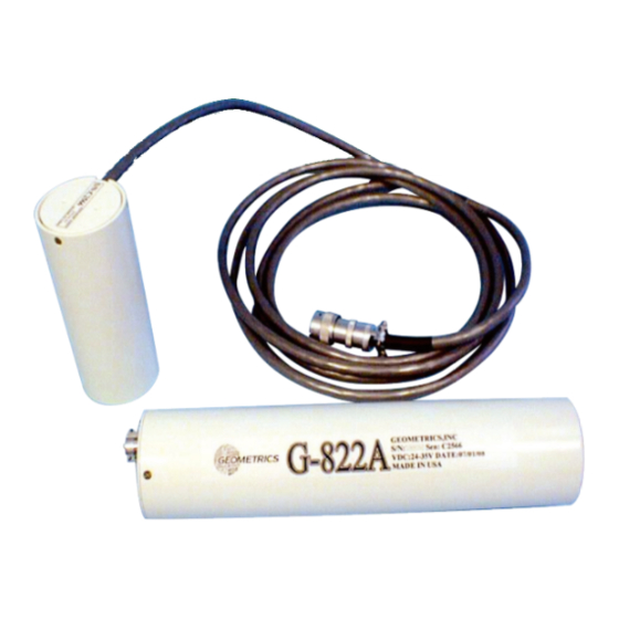
Geometrics G-822A Operation Manual
Cesium magnetometer
Hide thumbs
1
2
Table Of Contents
3
4
5
6
7
8
9
10
11
12
13
14
15
16
17
18
19
20
21
22
23
24
25
26
27
28
29
30
31
32
33
34
35
36
37
38
39
40
41
42
43
44
45
46
47
48
49
50
51
52
53
54
55
56
57
58
59
60
61
62
page
of
62
Go
/
62
Contents
Table of Contents
Troubleshooting
Bookmarks
Table of Contents
Table of Contents
1 Introduction
2 System Components
3 Performance
4 Installation
Sensor Orientation
Sensor Attachment
Environmental Considerations
Vibration
Electronic/Electromagnetic
Temperature
5 Operation
6 Trouble Shooting
7 G-823A Magnetometer
CM-201 Output Format
Commands
Detailed Command Descriptions
Cycle Time Set
A/D Channel Select/Enable
Baud Rate Change
Output Format Select
Julian Time Set
Julian Time Enable
Julian Output Format
Find Counters
Set Preamble Character
Echo Error Command
Interrogate Setup Command
Analog Channels
Reset Command
Jump to Debug
Power-Up Initialization
8 G-823B Magnetometer
9 Accessory Software
CM-201
Install.bat
Cm201Set.bat
Cm201.Bat
Cm201Go.exe
Commflip.exe
Batmenu.exe, Drawbox.exe, Gotoxy.exe, Yymmdd.exe, Foreach.exe, Getkey.com
Cesium Sensor Azimuth Program - Csaz
View201
Function Keys
Displaying Analog Channels
Display Channel ON/OFF [0/1]
Counter Number [0-2]
Analog Channel Number [0-5]
Unipolar/Bipolar [U/B]
Clip/Wrap [C/W]
Full Scale Set
Label
Set Trace Color
Appendix A1. Model G-822A Specifications
Appendix A2. Model G-823A Specifications
Appendix A3. Sensor Installations
Appendix A4. Cesium-Vapor Sensor Theory
Appendix A5. G-822A General Block Diagram of System Components
Appendix A6. G-823A General Block Diagram of System Components
Appendix A7. G-823B General Block Diagram of System Components
Advertisement
Quick Links
Download this manual
G-822A and G-823A & B
CESIUM MAGNETOMETER
27597-OM REV. B5
Operation Manual
COPYRIGHT © 2004
GEOMETRICS, INC.
2190 Fortune Drive, San Jose, CA 95131 USA
Phone: (408) 954-0522
Fax: (408) 954-0902
EMAIL:
sales@mail.geometrics.com
Table of
Contents
Previous
Page
Next
Page
1
2
3
4
5
Advertisement
Table of Contents
Need help?
Do you have a question about the G-822A and is the answer not in the manual?
Ask a question
Questions and answers
Related Manuals for Geometrics G-822A
Measuring Instruments Geometrics G-858BP Operation Manual
Cesium vapor magnetometer (108 pages)
Measuring Instruments GEOMETRICS GemPen User Manual
(14 pages)
Measuring Instruments GEOMETRICS G-877 Operation Manual
Marine magnetometer (49 pages)
Measuring Instruments GEOMETRICS G-824A Operation Manual
Cesium magnetometer (61 pages)
Measuring Instruments GEOMETRICS Memory-Mag G-857 Operation Manual
Proton precession magnetometer (78 pages)
Measuring Instruments Geometrics G857 Pocket Reference Manual
Magnetometer (2 pages)
Measuring Instruments Geometrics Memory-Mag G-856AX Operation Manual
Proton precession magnetometer (60 pages)
Measuring Instruments Geometrics G-864 User Manual
Cesium backpack magnetometer and cesium backpack gradiometer (60 pages)
Measuring Instruments Geometrics MagArrow User Manual
Uas deployable magnetometer (47 pages)
Measuring Instruments Geometrics SmartSeis Maintenance Manual
(18 pages)
Measuring Instruments GEOMETRICS MagArrow User Manual
Uas deployable magnetometer (39 pages)
Measuring Instruments Geometrics MagEx Quick Start Manual
Portable magnetometer (15 pages)
Measuring Instruments Geometrics MagEx Quick Start Manual
Portable magnetometer (9 pages)
Measuring Instruments Geometrics MetalMapper 2x2 Operation Manual
(69 pages)
This manual is also suitable for:
G-823a
G-823b
Table of Contents
Print
Rename the bookmark
Delete bookmark?
Delete from my manuals?
Login
Sign In
OR
Sign in with Facebook
Sign in with Google
Upload manual
Upload from disk
Upload from URL


Need help?
Do you have a question about the G-822A and is the answer not in the manual?
Questions and answers