
Related Manuals for ACI Laser DFL Ventus Marker

Summary of Contents for ACI Laser DFL Ventus Marker
- Page 1 LASER MARKING SYSTEMS Operating Instructions DFL Ventus Marker Standard Design Business Fibre OEM Version Laser Device Class 4 Mark your territory...
- Page 2 The manufacturer shall only be responsible for the safety characteristics of this device within the scope of the legally applicable regulations if it is operated by the user in accordance with the operating instructions and repaired by ACI Laser GmbH itself or someone appointed by and acting under the instructions of ACI Laser GmbH.
-
Page 3: Table Of Contents
Table of Contents Table of Contents Introduction ..........................7 Important Information ........................7 Intended Use ..........................8 Improper Use ..........................9 Notices in the Document ......................9 Warranty ............................11 Technical Customer Service ..................... 12 Safety ............................13 Basic Safety Instructions ......................13 Functional safety ........................ - Page 4 Table of Contents Technical Data ..........................27 Laser device ..........................27 Connection values ........................27 Interfaces ..........................27 Scan unit ........................... 28 Focusing objectives (optional) ....................28 Dimensions and weight ......................29 Operation and storage conditions .................... 30 Scope of Delivery ........................30 Installation ..........................
- Page 5 Table of Contents 5.4.2 Connection ........................... 48 Power connection ........................48 Connection between the laser head and the supply unit ............48 Connection with the PC ......................48 Checking the Installation ......................49 Operation ............................ 50 Operating and Display Elements ....................50 Operating elements ........................
- Page 6 Table of Contents...
-
Page 7: Introduction
• optimization for the intended purpose. The DFL Ventus Marker is a state-of-the-art device. The EC Declaration of Incorporation and the EC Declaration of Conformity confirm that the manufacturer has complied with the relevant directives. The CE symbol is located on the type plate. -
Page 8: Intended Use
• The DFL Ventus Marker marking system is intended to be used exclusively for marking applications in conjunction with the associated Magic Mark software. The performance parameters must be adapted to suit the properties of the materials to be marked. -
Page 9: Improper Use
Important Information Improper Use All other uses other than use for the intended purpose, including that with other control software, shall be deemed to be improper use. The laser marking device must not be used by: • persons who have not read or understood these operating instructions, •... - Page 10 Important Information DANGER RISK OF DEATH OR SERIOUS INJURIES! Indication of an imminent danger, which will result in death or serious injuries if the appropriate precautionary measures are not taken. WARNING DANGER OF INJURIES AND/OR RISK OF PROPERTY DAMAGE. Indication of an immediately impending hazard which can cause serious injuries or property damage if the appropriate precautionary measures are not taken.
-
Page 11: Warranty
Important Information Warranty The manufacturer guarantees that the product does not have any manufacturing or mate- rial defects. The warranty period shall be 12 months from the dispatch date in as far as no other con- tractual ruling has been made. The scope of warranty is limited to the repair or replacement of the product supplied by the manufacturer. -
Page 12: Technical Customer Service
Important Information Technical Customer Service ACI Laser GmbH Steinbrüchenstraße 14 D-99428 Grammetal OT Nohra Germany Phone: +49 3643 4152-0 Fax: +49 3643 4152-77 service@ACI-Laser.de www.ACI-Laser.de NOTICE The laser device may only be maintained and repaired by the manufacturer. Any manipulations on the device or breaking the warranty seal will void any claims... -
Page 13: Safety
14 years, at the latest, in order to maintain performance level e. Laser class As an OEM component, the DFL Ventus Marker is a class 4 laser marking device accord- ing to DIN EN 60825-1 "Safety of Laser Devices": •... -
Page 14: Emissions
Safety The following measures must be taken in order to be able to categorize the DFL Ventus Marker as a class 1 laser device (accessible laser radiation is harmless: • Ensure that the entire beam path to the work piece is shielded beam-tight. •... -
Page 15: General
Safety - other reaction products to be given off from the material surface. These may be toxic, depending upon the material being processed. The operating company must therefore provide effective extraction. Information about this can be found, for example, in the VDI guideline 2262 1...3 "Air Quality in the Work Place". -
Page 16: Operation
Safety The main beam is simulated by a pilot laser. The laser is not harmful to the skin. The eyes are protected by the natural blink reflex. • Before starting up, always plug the fiber laser cable into the socket provided, before do- ing so remove the protective caps and any dirt. -
Page 17: Labels At The Device
Safety Labels at the Device Warning notices The warning notices on the device point out possible hazards from the laser and provide information about the basic performance data of the laser devices. • On the top of the enclosure of the laser head (1): AVOID EXPOSURE TO RADIATION EMISSION OF VISIBLE AND INVISIBLE LASER RADIATION... - Page 18 Safety • On the fiber laser cable (3 and 4): LASER APERTURE HANDLE WITH CARE • On the rear side of the design variant 1 casing (5 and 6): For design variant 2, there are no warning signs attached on the rear of the housing.
-
Page 19: Type Plates
• fuse for the device. Small type plate (1, 2 and 3) MARKER Model: Serial Number: 2001VIII-0001 Manufacturer: ACI Laser GmbH Date of Manufacturing: 01/2020 Line Voltage: 100-240VAC, 50-60Hz Max. rated Power: 550W Fuse: 230V/2 x 2,5AT 110V/2 x 5,0AT Vor Öffnen des Gehäuses Netzstecker ziehen! -
Page 20: Description
Description Overview The DFL Ventus Marker consists of a laser head and a supply unit, which are connected by a fiber laser cable. The maximum distance is 3 m. The laser head can be mounted directly on the supply unit or separately. -
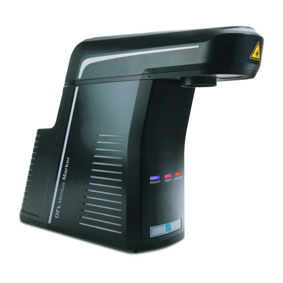
Page 21: Views Of The Device
Description Views of the Device Laser head view Front view Rear view design variant 1 Rear view design variant 2 (1) multi function display (2) interfaces (3) mounting surface (3) bolt-on point for the supply unit (5) objective (laser beam outlet) (6) focus finder... -
Page 22: Supply Unit View
Description Supply unit view (1) enclosure (2) interfaces (3) side ventilation slits (air inlet), on both sides (4) rear ventilation slits (air outlet) (5) fiber laser cable connection... -
Page 23: Intended Purpose
• minimal stress on the material and minimal change in its properties. These requirements are optimally fulfilled by the DFL Ventus Marker. The laser marking device is a highly-integrated marking system. The device consists of two assemblies: the supply unit and the laser head. -
Page 24: Principle Of Operation
Description In contrast to other comparable systems, the DFL Ventus Marker guarantees: • The easiest integration into existing production lines because of its small dimensions and low weight. • Increased operational safety by the elimination of complex water-air cooling units. -
Page 25: Fiber Laser Beam Generation
Description The laser beam source integrated into the supply unit generates the laser radiation, which is transmitted to the laser head via a passive transport fiber. The laser beam generated in this way is widened in the laser head by a lens system, and then forms the working beam of the laser system. - Page 26 Description In the event of the following errors: • exceeding the defined time period of 200 ms upon opening or closing the diaphragm, • short circuit or interruption of the interlock circuits, • exceeding the defined time period of 150 ms upon switching the two interlock circuits, •...
-
Page 27: Technical Data
Description Technical Data Laser device Diode-pumped fiber laser (Yb:fiber) Operating mode: pulsed Wave lengths: 1064 nm ± 5 nm Laser power (maximum): 20 W - 70 W, system dependent Beam quality M < 1.3 to < 3.7, system dependent Peak power (maximum): 9 kW - 20 kW, system dependent Pulse energy (maximum): 0.7 mJ - 1.3 mJ, system dependent... -
Page 28: Scan Unit
Description - 8 digital inputs - 8 digital outputs - differential inputs for "Marking on the fly" Scan unit Scanning speed: < 10 m/sec Focusing objectives (optional) F-Theta 100 Spot diameter 25 µm Marking field size: 60 mm x 60 mm Focus shift: ±... -
Page 29: Dimensions And Weight
Description Dimensions and weight Laser head Length x width x height: 595 mm x 203 mm x 133 mm Weight: 9 kg Supply unit 223.5 Length x width x height: 646 mm x 224 mm x 451 mm Weight: 26 kg... -
Page 30: Operation And Storage Conditions
Description Operation and storage Operating temperature: 25 °C ± 10 °C conditions Storage temperature: 10 °C - 50 °C Air humidity: 30% - 85%, without condensation Scope of Delivery • Laser head, • supply unit, • fiber laser cable of a length of 3 meters, •... -
Page 31: Installation
The laser marking device is delivered in a packaging which meets UPS "falling regula- tions". From the inside outwards: • laser device DFL Ventus Marker with the components: laser head, supply unit and fiber laser cable, • foam grid, •... - Page 32 Installation Remove the foam grid. Place the laser head and the supply unit on a flat surface. CAUTION Do not hold the supply unit by the edge above the interfaces. Remove the accessories and place them down. Check the scope of delivery for completeness. NOTICE Store the packaging material in a safe place in case the device has to be returned to the manufacturer under warranty for maintenance and repair work.
-
Page 33: Mechanical Installation
Installation Mechanical Installation The special design of the DFL Ventus Marker enables it be attached optionally either to the laser head on the supply unit or directly in a system. The distance to the supply unit is a maximum of 3 meters. -
Page 34: Assembly Of The Laser Head To The Plant
Installation Assembly of the laser head to the The mounting surface (2) on the underside of the laser head is used to attach it mechan- plant ically to a system. The position of the bore holes (measured in mm) for •... -
Page 35: Assembly Of The Laser Head To The Supply Unit
Installation Assembly of the laser head to the Take off the enclosure from the supply unit. supply unit Put on the laser head. Fixate the laser head by hand tightening the two setscrews (1). Screw in the two screws (2). -
Page 36: Focusing
Installation Focusing NOTICE A defined distance between the objective of the scan head and the work piece must be set in order to focus the laser beam optimally on the surface of the work piece. The distance (A) between the lower edge of the scan unit (1) and the surface of the work- piece (2) depends upon the type of objective used: •... -
Page 37: Adjusting The Focus Finder
Installation Adjusting the focus finder If focus finder and pilot laser do not coincide, the focus finder can be readjusted with the aid of the two adjustment screws (1). If the lens has been changed, the focus finder must be adjusted accordingly: Remove the 3 screws (3) and remove the protective window (2), under which the fo- cus finder is accessible. -
Page 38: Connecting The Fiber Laser Cable
Installation Connecting the fiber laser cable Connect the laser head to the supply unit by the fiber laser cable. CAUTION The fiber laser cable can be damaged by incorrect handling. Do not kink or twist cables, or roll them up too tightly. Minimum kink radius 75 mm Minimum loop length... - Page 39 Installation Plugging the fiber laser cable into the laser head (design variant 2): Loosen the 4 screws (2) on the frame with sealing gaskets (1). Insert the fiber laser cable connector (3), align the markings with each other. Secure the connector by screwing in the 2 clamping screws (4) on the underside of the laser head.
-
Page 40: Marking Software Installation
Installation Marking Software Installation • Minimum hardware requirements PC with 64 bit operating system Windows 7 or 10, • CD ROM drive, • 1 free USB 2.0 interface, • monitor with 1280 x 1024 pixels, • keyboard, mouse. If necessary, you will receive this additional information from the manufacturer. Installation Start the PC. -
Page 41: Electrical Installation
Installation Electrical Installation 5.4.1 Interfaces WARNING DANGER OF INJURIES AND/OR RISK OF PROPERTY DAMAGE! The device interfaces may only be connected to the plant by an electri- cian in cooperation with a laser safety officer! Laser head interfaces Design variant 1 Design variant 2 (1) supply cable connection 2 (to the supply unit) (2) supply cable connection 1 (to the supply unit) -
Page 42: Supply Unit Interfaces
Installation Supply unit interfaces (1) power input module with cold device plug socket and micro fuse drawer (2) interlock connection (3) optional trim module (4) power switch (5) supply cable connection 1 (to the laser head) (6) supply cable connection 2 (to the laser head) (7) laser control interface, 37-pin, sub-D, panel socket as an interface to the plant (8) USB 2.0 interface used for communication between control PC and laser marking device... -
Page 43: Interlock Connection
Installation Interlock connection INTL1_OUT INTL1_IN INTL2_OUT INTL2_IN SD-READY D-SUB-9F Interlock circuit 1 and 2 Pin 1, pin 6 INTL1_OUT, INTL1_IN external interlock circuit 1 Pin 2, pin 7 INTL2_OUT, INTL2_IN external interlock circuit 2 In order to integrate the laser marking device into an external, dual-channel, safety circuit, 2 potential-free independent safety switches must be wired between pin 1/6 and pin 2/7 (see image). - Page 44 Installation To this end, it must be ensured (mechanically) that both switches reliably within a period of 150 ms. Alternatively for the use of potential-free safety switches, it is possible to use a safety relay based on Performance Level e with appropriate wiring in accordance with the manufac- turer's specifications.
-
Page 45: Laser Control Interface
Installation Laser control interface The laser control interface is a 37-pin, 2-row sub-D panel socket. Depending upon the application case, the laser control interface may be wired by the user. D-SUB-37F EMISSION READY OUT1 OUT2 OUT3 OUT4 OUT5 OUT6 OUT7 OUT8 GND I/ O GND I/ O... - Page 46 Installation External emission light Pin 22 EMISSION 24 V, max. 200 mA, fused by poly fuse. Pin 22 carries 24 V when the shutter is open. The connected emission warning light signals danger from laser radiation. WARNING DANGER OF INJURIES AND/OR RISK OF PROPERTY DAMAGE FROM LASER RADIATION! Wiring this output is specified for operation in accordance with a class 4 laser.
-
Page 47: Optional Trim Module
Installation electronically protected, short-circuit proof, inductive loads may be connected. There is an internal freewheel diode. Pin 2, 4, 21 GND I/O Reference for all 24 V inputs and outputsv as well as READY and EMISSION The inputs can be queried during a marking cycle and so start a marking job. The freely programmable outputs can, for example, be used to indicate the end of an inscription. -
Page 48: Connection
Installation 5.4.2 Connection Power connection Ensure that the device power switch (1) is switched off. Connect the supplied power cable to the power input module (2) of the supply unit. Connect the power cable to an earthed socket. Connection between the laser Connect the laser head to the supply unit by the supply cables. -
Page 49: Checking The Installation
Installation Checking the Installation CAUTION RISK OF PROPERTY DAMAGE. Perform the following tests to avoid material damage. Please check the following points again before you bring your laser system into operation. • Have the mechanical and electrical installations been performed correctly and com- pletely? •... -
Page 50: Operation
Operation Operation Operating and Display Elements Operating elements The laser marking system just has a power switch (1) near the power input module. Multi function display Can the current operating status of the laser marking device be seen on the multi function display (1) of the laser head and the function indicator on the supply unit with the ele- ments: Power, dark blue (2), Ready, orange (3) and Emission, yellow (4). - Page 51 Operation Multi function display Supply unit Conditon Meaning of the laser head function indicator Dark blue Power Dark blue Offline Laser initialising flashig Dark blue Power Dark Blue Offline Device switched on, Software not started or no communication Dark yellow Power Dark Blue Communication exists, Laser not activated...
-
Page 52: Starting The Laser Marking Device
Operation Starting the Laser Marking Device NOTICE Keep to the switching sequence on each start. Start the control PC. Wait until the operating system has completely loaded. Switch on the device power switch. NOTICE The interlock circuits must be open when switching on the device. Follow the Windows installation instructions during the initial commissioning. -
Page 53: Handling
Operation Handling The laser marking device is operated via the marking software. All operating sequences are controlled from the control PC via the laser control interface. All the parameters are exclusively entered on the keyboard of the control computer. NOTICE Detailed information for using the marking software is contained in the software manual provided. - Page 54 Operation Problem/Fault Possible cause Elimination Laser cannot be started Cable incorrectly plugged Check that the cable is seated properly. Interlock circuits closed Open the interlock circuits (must always be open upon system start-up). SD error Start the marking software and check status / error reports in the status bar, respectively in the message window, to receive detailed informa- tion.
-
Page 55: Specific Faults
Operation Problem/Fault Possible cause Elimination Laser does not pulse Incorrect laser parameters Check the laser parameter settings, the laser may be working in cw operation. Laser switches off automati- Environmental conditions do Check the environmental conditions. cally not meet the specifications Keep to the environmental conditions required. - Page 56 Operation Status/Error Trigger Message Evaluation per software Interlock fault Laser Safety Device SD interlock ERROR Display + Cut Off SD undervoltage Laser Safety Device SD ERROR internal under- Display + Cut Off voltage SD error Laser Safety Device SD internal ERROR Display + Cut Off Error +12V, <10V Laser Interface F...
-
Page 57: Maintenance And Repair
Maintenance and Repair Maintenance and Repair Care Perform the following care activities on the device at regular intervals. • Clean the objective. • Clean the ventilation slits of the covers. WARNING DANGER OF INJURIES AND/OR RISK OF PROPERTY DAMAGE. Ensure that the power plug has been pulled out before starting the cleaning tasks! -
Page 58: Cleaning The Objective
Maintenance and Repair Cleaning the objective A dirty objective reduces the transmission of the laser radiation. This leads to a reduction of the laser power on the work piece. The dirt can burn into the surface and damage the focusing objective. A protecting glass is therefore fixed in front of the objective by means of a threaded ring. -
Page 59: Cleaning The Ventilation Slits
If ambient air is heavily polluted, we recommend inserting and regularly chang- ing filter mats in the side covers. Suitable filter mats can be obtained from ACI Laser GmbH. Take off the enclosure. Remove the two fixing screws (3) from the top of the supply unit and the two screws (7) from the bottom. -
Page 60: Maintenance, Repair
Maintenance and Repair Maintenance, Repair The laser device does not contain any parts which can be maintained or repaired by the user. All maintenance and repair work must be performed exclusively by the manufacturer. The right to claim under warranty is lost as soon as third parties work on or modify the de- vice. -
Page 61: Scrap Disposal
Scrap Disposal Scrap Disposal ENVIRONMENT Protect the environment! For a fee, the customer will accept return of the laser device and dispose of it properly in a manner that is environmentally compatible. Environmentally sensible disposal of electrical and electronic equipment! Electrical and electronic equipment contains valuable materials that should be supplied to recycling or recovery. -
Page 62: Appendix
Appendix Appendix Saturation Vapour Pressure as a Function of the Temperature p´ [mbar] p´ [mbar] t [°C] t [°C] 17.04 33.60 18.17 35.64 19.36 37.79 20.63 40.04 21.96 42.42 23.37 44.91 24.86 47.54 26.42 50.29 28.08 53.18 29.82 56.22 31.66 To estimate the condensation temperature T , you need: •... - Page 63 Appendix = 25 °C, ϕ = 0,65%) Example calculation (T Proceed as follows: Determine the saturation vapour pressure p´ (p´ = 31,66 mbar) in the table for t = T = ϕ Calculate the vapour pressure p p´ = 0.65% x 31.66 mbar = 20.58 mbar Determine the value t = T = 18 °C) associated with p in the table = 20.63...
-
Page 64: Ec Declaration Of Incorporation
Representative for compiling technical documents: Mirko Wunderlich, Steinbrüchenstraße 14, 99248 Grammetal OT Nohra Signed on behalf of the manufacturer by: Nohra, 2019-02-01 ACI Laser GmbH Mirko Wunderlich Steinbrüchenstraße 14, 99428 Grammetal OT Nohra Geschäftsführer Commissioning is prohibited until it has been determined that the machine which the device is to be installed complies with the provisions of the directive on machinery. -
Page 65: Ec Declaration Of Conformity
EN 61000-3-2:2015-03 EN 61000-3-3:2014-03 EN 50581:2012 Representative for compiling technical documents: Mirko Wunderlich, Steinbrüchenstraße 14, 99248 Grammetal OT Nohra Signed on behalf of the manufacturer by: Nohra, 2019-02-01 ACI Laser GmbH Mirko Wunderlich Steinbrüchenstraße 14, 99428 Grammetal OT Nohra Geschäftsführer... - Page 66 Appendix...
-
Page 67: Index
Index Index Air humidity ..............................62 Air inlet ............................... 22 Air outlet ..............................22 Ambient temperature .......................... 15 Assembly ..............................33 Laser head to the plant ......................34 Laser head to the power unit ....................35 Beam path ..............................14 Beam quality .............................. - Page 68 Index EC Declaration of Conformity ........................65 EC Declaration of Incorporation ........................ 64 EMISSION ..............................46 Emission light ............................46 Emission warning light ..........................14 Emissions ..............................14 Enclosure ..............................22 Encoder, optional ............................47 Extraction ..............................15 Fault finding ............................... 53 Fiber laser beam generation ........................
- Page 69 Index Improper use ..............................9 Initial start-up ............................. 15 Inputs ................................. 46 Installation ..............................14 Check ............................49 Electrical ........................... 41 Marking software ........................40 Mechanical ..........................33 Instructions ..............................16 Intended use ..............................8 Interfaces ............................21 Interlock circuit ............................43 Interlock connection ........................27 Laser class ............................
- Page 70 Index Magic Mark ..............................8 Maintenance ..........................16 Maintenance intervals ..........................60 Manufacturer ............................. 19 Manufacturer address ..........................12 Marking job ..............................47 Marking on the fly ............................47 Marking software ............................52 Installation ..........................40 Mounting surface ............................21 Multi function display ...........................21 Objective lens ............................
- Page 71 Index Power consumption ..........................19 Power input module ........................... 48 Power supply connection ........................... 27 Power switch ..........................42 Principle of operation ..........................24 Production line ............................. 7 Pulse energy .............................. 27 Pulse forms ..............................27 Pulse lengths ............................. 27 Pulse repetition rate ........................... 27 READY ..............................
- Page 72 Index Supply unit ..............................23 Supply unit view ............................22 Switching on the device ..........................26 Switching sequence ..........................52 Technical data ............................27 Type plates ..............................19 Unpacking ..............................31 USB 2.0 interface ............................42 Ventilation slits ............................22 Cleaning ...........................
- Page 74 Operating Instructions for DFL Ventus Marker Standard Design Business Fibre Article number: 10001631 Version: EN 02/2019-02 ACI Laser GmbH Steinbrüchenstraße 14 D-99428 Grammetal OT Nohra Phone: +49 3643 4152-0 Fax: +49 3643 4152-77 info@ACI-Laser.de www.ACI-Laser.de Mark your territory...
Need help?
Do you have a question about the DFL Ventus Marker and is the answer not in the manual?
Questions and answers