
Subscribe to Our Youtube Channel
Related Manuals for dacell DN501A

Summary of Contents for dacell DN501A
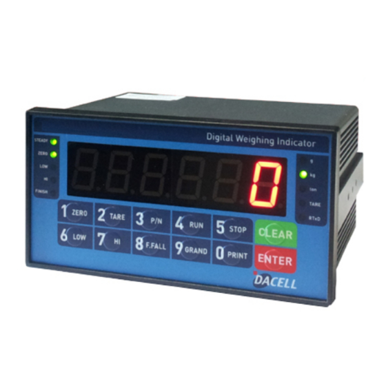
- Page 1 Digital Weighing Indicator DN501A DACELL CO.,LTD TEL : +82-43-260-2242 FAX : +82-43-260-2242 WEBSITE: http://www.dacell.com EMAIL : info@dacell.com...
-
Page 2: Table Of Contents
CONTENTS 1. Before Installation ---------------------------------- 2 Page 2. Introduction ---------------------------------- 3 Page 3. Specification ---------------------------------- 4 Page 4. Installation ---------------------------------- 10 Page 5. Set-Up ---------------------------------- 12 Page 6. Interface ---------------------------------- 25 Page 7. Error and Treatment ---------------------------------- 38 Page 1 / 41... -
Page 3: Before Installation
1-3. Copy Rights 1). All Right and Authority for this Manual is belonged to DACELL Co., Ltd. 2). Any kinds of copy or distribution without DACELL CO., Ltd’s permission will be prohibited. 1-4. Inquiries If you have any kinds of inquiries for this model, please contact with your local agent or Head Office. -
Page 4: Introduction
With 1port serial port communication and High Speed A/D conversion performance will lead you to precise weighing process. This “DN501A” Weighing Indicator is simple application model, and it can be used for “Truck Scale, Platform Scale, Tank Scale. Please review this instruction Manual and learn more about information about “DN501A”. -
Page 5: Specification
3. SPECIFICATION 3-1. Analog Input & A/D Conversion 0.45㎶ / Digit Input Sensitivity Load Cell Excitation DC 10V ( - 5V ~ + 5V ) Max. Signal Input Voltage Max.32mV [Zero] ±20PPM/℃ Temperature Coefficient [Span] ±20PPM/℃ Input Noise ±0.6㎶ P.P Input Impedance Over 10㏁... - Page 6 Serial Interface : RS422 / RS485 Option No.4 Option No.5 ※ Serial Interface (RS-232C) or Current Loop is Standard installed. And this DN501A indicator can’t use a BCD IN and OUT card. 3-5. Front Panel (Display & Key pad) 5 / 41...
- Page 7 3-5-1. Status Lamp (ANNUNCIATORS) : Green Color Lamp is “ON”. Steady When the weight is Steady, Lamp is turn on. When the current weight is Zero, Lamp is turn on. Zero (Displayed weight is Zero, Lamp is turn on.) Print When “Print”...
- Page 8 You can set each weighing process as a certain P/N. And you can call certain P/N with pressing this key. P/N save : Select P/N and Enter key input. P/N call : P/N + Number key + Enter Under each “Part No.(P/N)”, you can make more detailed sorting function with this key.
- Page 9 ※ Function Keys (Combined Key functions : key + other keys) For combined key function, you should press “CLEAR” or “ENTER” + other key within 2 sec. Time set value check or Change Date set value check or Change When auto print(if current weight is steady status) mode or manual print(if press “PRINT”...
- Page 10 3-6. Rear Panel ② ③ ④ ⑤ ① -Power ON/OFF Switch ①POWER -Fuse : AC 250V 2A -AC IN : AC110/220V selectable through DIP switch - OPTION BOARD install slot. ②OPTION 1,2 - ANALOG out, Serial I/F, etc -EXC + (+5V) PIN1 (RED) ③LOAD CELL -EXC - (-5V)
-
Page 11: Installation
4. INSTALLATION 4-1. External Dimension & Cutting Size (External Dimension) (unit : mm) Cutting Size 10 / 41... - Page 12 4-2. Formula to plan the precise weighing system This “DN501A” weighing controller’s Max. input sensitivity is 0.45㎶ / Digit. And for precise weighing system, the following formula must be satisfied. Caution : “Input sensitivity” means Min. output voltage variation of weighing part to change Cautions 1digit.
-
Page 13: Set-Up
Chapter 5. Set Up 5-1. Calibration Adjust weight balance between “Real weight” on the load cell(Weight Part) and “Displayed weight of Indicator”. When you replace LOAD CELL or Indicator, you have to do Calibration process once again 5-2. Test Weight Calibration (span Calibration) – Mode 1. - Applicable model : DN500 series Prepare at least 10% of Max. - Page 14 2-3. Under display, if press a keypad No. 2, it will be change the section 2. And, if press a keypad No. 3 or 4 or 1, it will be change the section 3 or 4 or 1. Then press key, and move to next step.”...
- Page 15 Input Capacity and press key, and move to next step. ※ Caution (Max. capacity value / division value) cannot be over 30,000(as Indicator resolution is 1/30,000). CAL _0_ Step 5. Zero Balance setting ( display) Make empty the scale part, and press key.
- Page 16 5-3. Simulation Calibration Mode (Without Test Weight) – Mode 2. - This calibration Method will be useful to make calibration more than 10ton capacity setting. - Guaranteed resolution will be 1/5,000 and if you need higher resolution, please make calibration with Test weight. Step 1.
- Page 17 CAPA XXXXXX Step 3. Max. Capacity of Load cell ( display) Input Max. Capacity of Scale with No. keys. - Under this step, input Total sum of each load cell’s Max. Capacity. (Not weighing Scale) - The Max. Capacity of load cell is stated on “Test report” or “Label”. - If you installed 4 load cells, and each load cell’s Max.
- Page 18 Step 5. Input Max. Output Rate (mV/V) value of load cell Input Max. Output Rate(mV/V) value of load cell with No. keys. - Under this step, input Max. Output rate(mV) of load cell. - If you installed a few pieces of load cells, the connection will be parallel, so the rated output of a few load cells are as same as single load cell’s rated output.
- Page 19 5-4. Function Setting – Mode 1. - Applicable model : DN500 series To make more accuracy performance of Digital Weighing Indicator, through this Function setting. Step 1. Enter to Function setting mode. TEST Turn on the Power + with pressing display SET-CAL key ...
- Page 20 5-4. Function List Function Contents Remark Decimal point setting Setting range : 0~3 Back up mode selection Setting range : 0, 1 Motion Band setting Setting range : 0~9 Zero Tracking setting Setting range : 0~9 Auto Zero Range setting Setting range : 00~99 Digital Filter setting Setting range : 00~49...
- Page 21 5-5. Function List detailed information. Decimal Point Setting ● No Decimal point place under Zero (0.0) place under Zero (0.00) place under Zero (0.000) Back up mode selection ● Normal mode Back up mode Motion Band Range setting This is set “Steady” acceptable range of weighing part. If there is vibration on weighing part, you can set this function and reduce the vibration effect on weighing process.
- Page 22 Zero key Operation Range selection Activated within 2% of Max. Capacity Activated within 5% of Max. Capacity Activated within 10% of Max. Capacity ● Activated within 20% of Max. Capacity Activated within 100% of Max. Capacity Tare key Operation Range selection Activated within 10% of Max.
- Page 23 Serial I/F Transference method setting ● Simplex Mode Duplex Mode / Command Mode Not Use External Display Mode ID No. setting ID No. setting with No. key. (01 ~99 settable) Data Transference Count setting About 40times/sec About 30times/sec About 20times/sec ●...
- Page 24 When Automatically print, Data output selection When weight reached Empty Range(F80 set value), Automatically ● print. - Check Empty Range Over than Empty Range, Steady Lamp is “ON”, Automatically Print. - Will not check Empty Range Print Format selection Continuous Print ●...
- Page 25 Other Setting EMPTY Range setting You can set “EMPTY” Range. Within set range, indicator will not display current weight and just display “Zero”. X.X.X.X.X.X. (0.0.0.0.1.0) “0.000” setting : When Net Zero, “Zero” status lamp and Near Zero relay will be output. “0.190”...
-
Page 26: Interface
Chapter 6. Interface 1. Rs-232C (Standard Installed) RS-232C Serial Interface is sensitive/weak for electric Noise. So, please isolate with AC power cable and use shield cable to reduce the electric noise effect. 1-1. Connection RXD 2 --------------------- Pin3 TXD TXD 3 --------------------- Pin2 RXD DN510N-Series Indicator DN500N-Series Indicator PC(D-Sub 9Pin) - Page 27 1-3. Data Protocol (Data Format 1. – Total 18byte) Header1 Header2 Data(8) unit ▶ Header 1 - OL : OVER LOAD or UNDER LOAD - ST : Weight Stable - US : Weight Unstable ▶ Header 2 - NT : Net Weight (Without TARE Weight) - GS : Gross Weight (With TARE Weight) ▶...
- Page 28 2. Current Loop Interface (Standard installed) “Current Loop” Interface is stronger for Electric Noise than “RS-232C” interface. So, it can be used for long distance communication.(About 100m long distance). 2-1. Connection 6 C/L --------------------------- RXD 7 C/L --------------------------- GND DN500N Series Indicator Remote Display 2-2.
- Page 29 3. Rs-422 Serial Interface (Option) RS-422/485 serial interface is more stable for electric noise effect compare with other communication method, using electric current difference. But, install isolated place from Power cable or other electric cables and wires, and please use shielded cable for better performance.
- Page 30 ▶ COMMAND MODE 1. READ COMMAND [Start(STX ), End(ETX ), Succeed(ACK ), Failed(NAK RxD & TxD Transfer & Response display Command PCIndicator (ASCII) Format (HEX) Date Data Response (ASCII) from (HEX) Indicator PCIndicator (ASCII) Format (HEX) Time Data Response (ASCII) from (HEX) Indicator...
- Page 31 Remark STX(1) ID(2) Command(4) Status1(2)SECTION(1) Status2(2) SECTION(1) Symbol(1) Weight (Include decimal point)(7) Unit(2) ETX(1) = Total 24 BYTE 30 / 41...
- Page 32 WRITE COMMAND [Start(STX ), End(ETX ), Succeed(ACK ), Failed(NAK & Transfer & Response display Command PCIndicator (ASCII) Format (HEX) TARE input Response (ASCII) from (HEX) Indicator PCIndicator (ASCII) Format (HEX) TARE RESET Response (ASCII) from (HEX) Indicator PCIndicator (ASCII) (HEX) Format ZERO input Response...
- Page 33 PCIndicator (ASCII) Format (HEX) Remark STX(1) ID(2) Command(4) Time(6) ETX(1) Time setting Response (ASCII) from (HEX) Indicator PCIndicator (ASCII) Format (HEX) Serial No. Remark STX(1) ID(2) Command(4) S/N(6) ETX(1) Change Response (ASCII) from (HEX) Indicator PCIndicator (ASCII) Format (HEX) Part No. Remark STX(1) ID(2) Command(4) P/N (2) ETX(1) Change...
- Page 34 PCIndicator (ASCII) Format (HEX) Hold RESET Response (ASCII) from (HEX) Indicator PCIndicator (ASCII) Format (HEX) Sub-Total Data Clear Response (ASCII) from (HEX) Indicator PCIndicator (ASCII) Format (HEX) Grand-Total Response (ASCII) Data Clear from (HEX) Indicator PCIndicator (ASCII) Format (HEX) “Auto key” input Response (ASCII) from...
- Page 35 4. Analogue Output (0~10V / Option) This Option card converts weight value to Analog Voltage output(0~10V) and transfers to external devices(Recorder, P.L.C), controlled by voltage output. 4-1. Specification - Output Valtage : 0~10V DC output - Accuracy : More than 1/1,000 ※As we convert Digital signal(1/30,000 accuracy) to Analogue, so the accuracy will be lower than Digital signal 4-2.
- Page 36 5. Analogue Output (4~20mA / Option) This Option card converts weight value to Analog Voltage output(4~20mA) and transfers to external devices(Recorder, P.L.C), controlled by voltage output. 5-1. Specification - Output Voltage : 4~20mA output (Max.2~22mA) - Accuracy : More than 1/1,000 - Temperature Coefficient : 0.01%/℃...
- Page 37 Serial Printer Interface (Standard). This interface can be connected all kinds of serial interface installed printer devices. But, programmed print format is specialized with our serial printer only. So, if you use different model, the format can be changed or not printed. 8-1.
- Page 38 7. Serial Print Format Single Continuous Print Print Format Format Sub-Total Print Format Grand Total Print Format 37 / 41...
-
Page 39: Error And Treatment
Chapter 7. Error and Treatment 1. TEST Mode TEST Mode No. Contents Detail information TEST 1. Analogue TEST mode This mode is Analogue testing This mode is Keypad testing or Analogue Option Card Test (4~20mA or 0~10v) - No.1 key : 4mA / 0V output TEST 2. - Page 40 2. Error and Treatment 2-1. Load Cell Installation Error Cause Treatment Remark 1).Input Resistance 1). Load cell broken of “EX+” and “EX- Measure Load cell “ about input/output resistance isolation 350& ~450& . of Load cell. resistance error 3). Weighing part Output Weight Value is 2).
- Page 41 2-2. Calibration Process Error Cause Treatment When Max.capacity/digit Re-input the Max. Capacity, less than 20.00 Err 01 value is over 20.00 (Max. Capacity / Digit) Standard weight value is Re-input Standard weight value with Number Err 04 over than Max. Capacity keys, under Max.
Need help?
Do you have a question about the DN501A and is the answer not in the manual?
Questions and answers