Table of Contents
Advertisement
Quick Links
SERVICE MANUAL
BUILT IN WINE CELLAR
MODEL : SKSCW181RP
SKSCW241RP
MFL67262420
Any reproduction, duplication, distribution (including by way of email, facsimile or other electronic means), publication,
modification, copying or transmission of this Service Manual is STRICTLY PROHIBITED unless you have obtained
the prior written consent of the SIGNATURE KITCHEN SUITE entity from which you received this Service Manual.
The material covered by this prohibition includes, without limitation, any text, graphics or logos in this Service Manual.
Copyright ©
2018 - 2019
SIGNATURE KITCHEN SUITE. All rights reserved. Only training and service purposes.
CONFIDENTIAL
www.signaturekitchensuite.com
Advertisement
Table of Contents
Troubleshooting

Related Manuals for Signature Kitchen Suite SKSCW181RP


Summary of Contents for Signature Kitchen Suite SKSCW181RP
- Page 1 Service Manual is STRICTLY PROHIBITED unless you have obtained the prior written consent of the SIGNATURE KITCHEN SUITE entity from which you received this Service Manual. The material covered by this prohibition includes, without limitation, any text, graphics or logos in this Service Manual.
-
Page 2: Table Of Contents
16. Multi Duct ....................................64 17. Defrost Sensor ...................................65 18. Barrier ....................................66 9. SEALED SYSTEM REPAIR METHOD OF REFRIGERATOR WITH R600A REFRIGERANT ...........67-73 10. EXPLODED VIEW ................................74-81 Copyright © 2018-2019 SIGNATURE KITCHEN SUITE. - 2 - All rights reserved. Only training and service purposes. -
Page 3: Safety Precautions
3. Take caution not to get water near any electrical components. 4. Use exact replacement parts. 5. Remove any objects from the top prior to tilting the product. Copyright © 2018-2019 SIGNATURE KITCHEN SUITE. - 3 - All rights reserved. Only training and service purposes. -
Page 4: Product Standards
DC 12V DC 12V standard" condenser Inside lamp 15.4W 28.2W Main Fuse 125V / 10A 125V / 10A Valve DC 12V DC 12V Copyright © 2018-2019 SIGNATURE KITCHEN SUITE. - 4 - All rights reserved. Only training and service purposes. -
Page 5: Circuit Diagram
W3 LED PWM LIGHT DEFROSTING FUSE-M FUSE-M BO/WH HEATER BO/BL YL/BK W2 DEFROSTING HEATER W3 FAN WH/BK BL/WH W3 DEFROSTING HEATER W1 DEFROSTING HEATER GROUNDING GR/YL Copyright © 2018-2019 SIGNATURE KITCHEN SUITE. - 5 - All rights reserved. Only training and service purposes. - Page 6 DÉGIVRAGE W1 BO/BL YL/BK CHAUFFAGE DE DÉGIVRAGE W2 VENTILATEUR W3 WH/BK BL/WH CHAUFFAGE DE DÉGIVRAGE W3 CHAUFFAGE DE DÉGIVRAGE W1 MISE À TERRE GR/YL Copyright © 2018-2019 SIGNATURE KITCHEN SUITE. - 6 - All rights reserved. Only training and service purposes.
-
Page 7: Specifications
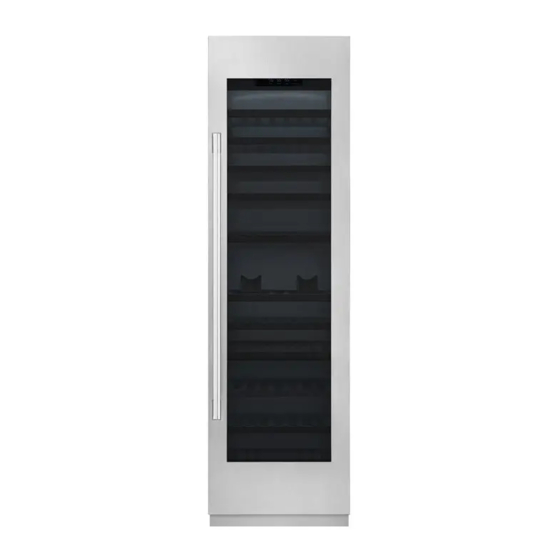
28 1/8"(713mm) Door Open 115º (F) 20 1/2"(520mm) 26 1/2"(659mm) Height Min (G) 83 1/2"(2121mm) 83 1/2"(2121mm) Max (H) 84 1/2"(2146mm) 84 1/2"(2146mm) Copyright © 2018-2019 SIGNATURE KITCHEN SUITE. - 7 - All rights reserved. Only training and service purposes. - Page 8 ● Parts MODEL : SKSCW181RP Control Panel LED Interior Lighting Storage Rack Zone Divider LED Interior Lighting Copyright © 2018-2019 SIGNATURE KITCHEN SUITE. - 8 - All rights reserved. Only training and service purposes.
- Page 9 ● Parts MODEL : SKSCW241RP Control Panel LED Interior Lighting Zone Divider LED Interior Lighting Storage Rack Zone Divider LED Interior Lighting Copyright © 2018-2019 SIGNATURE KITCHEN SUITE. - 9 - All rights reserved. Only training and service purposes.
-
Page 10: Micom Function
55˚F 54˚F 53˚F 52˚F 51˚F 50˚F 49˚F 48˚F 47˚F 46˚F 45˚F 44˚F 43˚F 42˚F 41˚F 64˚F 63˚F 62˚F 61˚F 60˚F 59˚F 58˚F 57˚F 56˚F Temper ature Copyright © 2018-2019 SIGNATURE KITCHEN SUITE. - 10 - All rights reserved. Only training and service purposes. - Page 11 - Wi-Fi Disconnecting : Wi-Fi Icon turns off after 3 min. Power : The Power Icon always on. If the power button is pressed and hold for 3 sec., it turns off. Copyright © 2018-2019 SIGNATURE KITCHEN SUITE. - 11 -...
-
Page 12: Trouble Shooting
Check the LED blinking times If the Comp is normal, (Refer to the next chapter for LED blinking and actions.) the LED does not blink. Copyright © 2018-2019 SIGNATURE KITCHEN SUITE. - 12 - All rights reserved. Only training and service purposes. - Page 13 IPM Error Communication Error - Not Cooling (LED No Blinking) PCBA Comp. Test Mode Output About 5min Replace PCB Action? 1 Input > 60V Copyright © 2018-2019 SIGNATURE KITCHEN SUITE. - 13 - All rights reserved. Only training and service purposes.
- Page 14 → Restart every 30 seconds after compressor off. Test Mode LED 1 Blinks LED 1 Blinks Reset About 5min Replace PCB 1 Input Copyright © 2018-2019 SIGNATURE KITCHEN SUITE. - 14 - All rights reserved. Only training and service purposes.
- Page 15 Do not operate Harness connection Comp.? Compressor is operate intermittently Check Comp. Check the leakage and cycle Stroke Trip Recheck Reset occur? Replace Compressor Copyright © 2018-2019 SIGNATURE KITCHEN SUITE. - 15 - All rights reserved. Only training and service purposes.
- Page 16 Protection Logic (No Connect Trip) Check Do not operate Harness connection Comp.? Check Comp. Replace PCB No Connect Trip Recheck Reset occur? Replace Compressor Copyright © 2018-2019 SIGNATURE KITCHEN SUITE. - 16 - All rights reserved. Only training and service purposes.
- Page 17 → Logic: Restart every 90 seconds after compressor off. Test Mode LED 4 Blinks LED 4 Blinks Reset About 5min Replace PCB 1 Input Copyright © 2018-2019 SIGNATURE KITCHEN SUITE. - 17 - All rights reserved. Only training and service purposes.
- Page 18 Protection Logic (Locked Piston Trip) Do not operate Comp.? Replace Reset Compressor Do not operate Clogging the Cycle? Comp.? Repair Recheck Sealed system Copyright © 2018-2019 SIGNATURE KITCHEN SUITE. - 18 - All rights reserved. Only training and service purposes.
- Page 19 Compressor failure Current trip Recheck Reset occur? Check the Do not operate Clogging the Cycle? leakage and cycle Comp.? Repair Replace Sealed system Compressor Copyright © 2018-2019 SIGNATURE KITCHEN SUITE. - 19 - All rights reserved. Only training and service purposes.
- Page 20 → Logic : After the Comp. Off every 20 seconds restart Comp. Test Mode LED 7 Blinks LED 7 Blinks Reset About 5min Replace PCB 1 Input Copyright © 2018-2019 SIGNATURE KITCHEN SUITE. - 20 - All rights reserved. Only training and service purposes.
- Page 21 → Logic : Only LED blinking without the Comp. Off (Comp. is operate command before communication error) Test Mode LED 8 Blinks LED 8 Blinks Reset About 5min Replace PCB 1 Input Copyright © 2018-2019 SIGNATURE KITCHEN SUITE. - 21 - All rights reserved. Only training and service purposes.
- Page 22 → To judge whether there is any issue with the PCB operation, check the PCB output voltage. Normal: Voltage 80[V] or higher output at (COMMON,POWER) or (COMMOM,SAVE) Copyright © 2018-2019 SIGNATURE KITCHEN SUITE. - 22 - All rights reserved. Only training and service purposes.
- Page 23 Harness Connection Check Check Check the Resistance the Resistance Comp. (point B) (point D) terminal Replace Harness Connection error Connection error Compressor failure Copyright © 2018-2019 SIGNATURE KITCHEN SUITE. - 23 - All rights reserved. Only training and service purposes.
- Page 24 Mode Resistance 14 ~17 Power(①) Save(②) 20 ~23 Multi Tester Earth Check insulation break-down ② ① Multi Tester FMA102NAMA Copyright © 2018-2019 SIGNATURE KITCHEN SUITE. - 24 - All rights reserved. Only training and service purposes.
-
Page 25: Trouble Shooting With Error Display
E CF Fan Motor Abnormal Communication Short ior Open E CO E CO Communication Circuit (Display ↔ Main PCB) 18 Wine 24 Wine Copyright © 2018-2019 SIGNATURE KITCHEN SUITE. - 25 - All rights reserved. Only training and service purposes. - Page 26 CON2 CON1 CON202 CON5 CON6 CON201 CON7 CON10 CON8 7-3. PCB Picture - Display PCB P/N : EBR850083 EBR852442 EBR852442 EBR852443 18inch 24inch Copyright © 2018-2019 SIGNATURE KITCHEN SUITE. - 26 - All rights reserved. Only training and service purposes.
- Page 27 W3 LED LIGHT 23ºF / -5ºC GY/RD 32ºF / 0ºC WH/BK 3WAY/4WAY VALVE 41ºF / 5ºC 50ºF / 10ºC 19.5k 59ºF / 15ºC Copyright © 2018-2019 SIGNATURE KITCHEN SUITE. - 27 - All rights reserved. Only training and service purposes.
- Page 28 Is the sensor connection normal? refrigerator Go to 6 Check the Sensor resistance. Is resistance OFF (Sensor open)? Reconnect or repair the connector Copyright © 2018-2019 SIGNATURE KITCHEN SUITE. - 28 - - 28 - All rights reserved. Only training and service purposes.
- Page 29 23ºF / -5ºC W3 LED LIGHT 32ºF / 0ºC GY/RD WH/BK 3WAY/4WAY 41ºF / 5ºC VALVE 50ºF / 10ºC 19.5k 59ºF / 15ºC Copyright © 2018-2019 SIGNATURE KITCHEN SUITE. - 29 - All rights reserved. Only training and service purposes.
- Page 30 Is the sensor connection normal? Go to 7 Check the Sensor resistance. Is resistance OFF (Sensor open)? Orange & Orange Reconnect or repair the connector Copyright © 2018-2019 SIGNATURE KITCHEN SUITE. - 30 - All rights reserved. Only training and service purposes.
- Page 31 [F2]4 pin & 8 pin BL/RD W2 LED PWM LIGHT [F3]20 pin & 24 pin SB/BK W3 LED PWM LIGHT BO/WH BO/BL YL/BK W3 FAN WH/BK BL/WH Copyright © 2018-2019 SIGNATURE KITCHEN SUITE. - 31 - All rights reserved. Only training and service purposes.
- Page 32 [F2]4 pin & 8 pin Fan motor Rotate fan using hand. [F3]20 pin & 24 pin It feel sticky? Fan Motor Explain to customer Copyright © 2018-2019 SIGNATURE KITCHEN SUITE. - 32 - All rights reserved. Only training and service purposes.
- Page 33 HYGIENE LED LIGHT W2 FAN WH/RD BL/RD W2 LED PWM LIGHT SB/BK W3 LED PWM LIGHT BO/WH BO/BL YL/BK W3 FAN WH/BK BL/WH Copyright © 2018-2019 SIGNATURE KITCHEN SUITE. - 33 - All rights reserved. Only training and service purposes.
- Page 34 19 pin & 23 pin Change the Check the Fan motor. Fan motor Rotate fan using hand. It feel sticky? Fan Motor Explain to customer Copyright © 2018-2019 SIGNATURE KITCHEN SUITE. - 34 - All rights reserved. Only training and service purposes.
-
Page 35: Door
OUTDOOR SENSOR KNOCK ON CON5 BO/WH SENSOR 1 Not 0V, 5V 4 pin & 8 pin KNOCK ON SENSOR 2 STEPPING MOTOR DAMPER Copyright © 2018-2019 SIGNATURE KITCHEN SUITE. - 35 - All rights reserved. Only training and service purposes. - Page 36 CON101 CON5 Voltage [V] 2 pin & 3 pin 0V, 5V CON5 4 pin & 8 pin 0V, 5V CON101 Explain to customer Copyright © 2018-2019 SIGNATURE KITCHEN SUITE. - 36 - All rights reserved. Only training and service purposes.
- Page 37 2 pin & 4 pin KNOCK ON BO/WH SENSOR 1 CON103 Not 0V, 5V KNOCK ON 3 pin & 4 pin SENSOR 2 STEPPING MOTOR DAMPER Copyright © 2018-2019 SIGNATURE KITCHEN SUITE. - 37 - All rights reserved. Only training and service purposes.
- Page 38 Check the voltage. Display Is CON103 2 pin & 4 pin voltage 0V or 5V? CON103 Voltage [V] CON103 pin & 4 0V, 5V Copyright © 2018-2019 SIGNATURE KITCHEN SUITE. - 38 - All rights reserved. Only training and service purposes.
- Page 39 W3 DEFROSTING SENSOR W1 LED LIGHT 23ºF / -5ºC 37.5k W2 LED LIGHT W3 LED LIGHT 32ºF / 0ºC GY/RD WH/BK 3WAY/4WAY VALVE Copyright © 2018-2019 SIGNATURE KITCHEN SUITE. - 39 - All rights reserved. Only training and service purposes.
- Page 40 (Push the button 1 time) Check the F Open the fresh food door and Fan Motor Check for air flow Go to 5 Copyright © 2018-2019 SIGNATURE KITCHEN SUITE. - 40 - All rights reserved. Only training and service purposes.
- Page 41 Voltage [V] CON7 3 pin & 7 pin Not 0V, 5V 4 pin & 8 pin 20 pin & 24 pin Explain to customer Copyright © 2018-2019 SIGNATURE KITCHEN SUITE. - 41 - All rights reserved. Only training and service purposes.
- Page 42 W3 LED PWM LIGHT BO/WH *PWM Control Voltage range BO/BL YL/BK W3 FAN LED Lamp Voltage [V] WH/BK BL/WH Closed 0~2V White &Yellow Open 5.7~12.6V Copyright © 2018-2019 SIGNATURE KITCHEN SUITE. - 42 - All rights reserved. Only training and service purposes.
- Page 43 LED Lamp Is it 5.7~12.6V? (While door open) CON7 *PWM Control Voltage range Voltage [V] Explain to customer CON7 5.7~12.6V All LED PART Copyright © 2018-2019 SIGNATURE KITCHEN SUITE. - 43 - All rights reserved. Only training and service purposes.
- Page 44 1) Release the spring on the hinge. Loosen the screw from l to 0 18,24 Wine - Right 2) Unscrew (1.) and remove (2.) the door. 3) Remove the hinges. 4) Assembly is reverse order. Copyright © 2018-2019 SIGNATURE KITCHEN SUITE. - 44 - All rights reserved. Only training and service purposes.
- Page 45 2) Remove 3 screws to pull out the Cover machinary room (Wine-Right Hinge) 3) Remove the 2 screws to pull out the Cover,PCB Copyright © 2018-2019 SIGNATURE KITCHEN SUITE. - 45 - All rights reserved. Only training and service purposes.
- Page 46 5) Remove the 2 screws to detach the Holder Bracket 6) Detach the harness from the main PCB 7) Assembly is reverse order. Copyright © 2018-2019 SIGNATURE KITCHEN SUITE. - 46 - All rights reserved. Only training and service purposes.
-
Page 47: Top Cover
Left side is fixed by this rib. So the cover need to be pull to disassemble the rib from bracket. 4) Assembly is reverse order. Copyright © 2018-2019 SIGNATURE KITCHEN SUITE. - 47 - All rights reserved. Only training and service purposes. -
Page 48: Door Switch / Sds Pcb / Temperature Sensor
3) Pull out the Top,Cover and replace the defect part. (If the Door switch needs to be replaced, you can replace the ① . Copyright © 2018-2019 SIGNATURE KITCHEN SUITE. - 48 - All rights reserved. Only training and service purposes. -
Page 49: Machine Room Cover
2) Remove the 1 Screw located at under the Hinge 3) Remove 2 Screws located at opposite the hinge. 4) Pull out the cover machinery room. Copyright © 2018-2019 SIGNATURE KITCHEN SUITE. - 49 - All rights reserved. Only training and service purposes. -
Page 50: Machine Room Cycle
If SVC the Guide Fan, Work in current state. And Refer to the Page (4/4) Caution : When handling the PIpe, be careful with the Pipe Crack. Copyright © 2018-2019 SIGNATURE KITCHEN SUITE. - 50 - All rights reserved. Only training and service purposes. - Page 51 If not, it cause a risk of leaks in customer’s furniture and floor. ※ GR-1137GPNM, GR-3137GPNM Machine rooms are Same structure. Refer to next page exploded View. Copyright © 2018-2019 SIGNATURE KITCHEN SUITE. - 51 - All rights reserved. Only training and service purposes.
- Page 52 ▪ Pipe,Joint -MGE64934801 ▪ Tube Assembly, Drain - 5251JA3004E GR-3137GPNM (24W) ▪ Valve Assembly,Pipe -AJU75332501 ▪ Pipe, Joint -MGE64934802 ▪ Tube Assembly, Drain -5251JA3004E Copyright © 2018-2019 SIGNATURE KITCHEN SUITE. - 52 - All rights reserved. Only training and service purposes.
- Page 53 3) Disassemble the Guide fan Assembly from the Refrigerator. - Reassemble in reverse order of disassembly. - Do not miss the Damper Rubber Located on Screw Customized. Copyright © 2018-2019 SIGNATURE KITCHEN SUITE. - 53 - All rights reserved. Only training and service purposes.
-
Page 54: Wi-Fi
4) Remove the WiFi module from the Cover front. - Remove the 1 Screw 5) Separate the WiFi module housing from 6) Assembly is reverse order. the Main PCB housing. Copyright © 2018-2019 SIGNATURE KITCHEN SUITE. - 54 - All rights reserved. Only training and service purposes. -
Page 55: Power Cord
2) Remove the earth screw and power cord screw. Power cord screw earth screw 3) Separate the Power Cord housing on the top. 4) Assembly is reverse order. Copyright © 2018-2019 SIGNATURE KITCHEN SUITE. - 55 - All rights reserved. Only training and service purposes. -
Page 56: Main Pcb
2) Remove the Cover machinery and Cover front. 3) Remove the earth screw that is located at the left side. Main PCB earth screw Copyright © 2018-2019 SIGNATURE KITCHEN SUITE. - 56 - All rights reserved. Only training and service purposes. - Page 57 ④ ① ⑥ ⑤ ⑨ 5) Remove the 2 screws. 6) Move Main PCB to the right and pull out the Main PCB. Copyright © 2018-2019 SIGNATURE KITCHEN SUITE. - 57 - All rights reserved. Only training and service purposes.
-
Page 58: Control Panel
※ If you have a problem to remove top duct screws by Guide Rail. You need to remove the both rail on the top. Copyright © 2018-2019 SIGNATURE KITCHEN SUITE. - 58 - All rights reserved. Only training and service purposes. -
Page 59: Shelf
2) Raise up and pull the Shelf by this direction ① Raise it up ② Pull in this direction 3) Assembly is reverse order. Copyright © 2018-2019 SIGNATURE KITCHEN SUITE. - 59 - All rights reserved. Only training and service purposes. -
Page 60: Slide Rail
4) Raise it up and pull Slide Rail by this direction ① Raise it up ② Pull in this direction 5) Assembly is reverse order. Copyright © 2018-2019 SIGNATURE KITCHEN SUITE. - 60 - All rights reserved. Only training and service purposes. -
Page 61: Holder Rail
4) Raise it up and pull Slide Rail by this direction ① Raise it up ② Pull in this direction 5) Remove 2 Screw completely 6) Assembly is reverse order. Copyright © 2018-2019 SIGNATURE KITCHEN SUITE. - 61 - All rights reserved. Only training and service purposes. -
Page 62: Top Duct
2) Remove 3 (or 2) Screws 3) Pull down the Top Duct and Separate the Housing and Remove the Top Duct 4) Assembly is reverse order. Copyright © 2018-2019 SIGNATURE KITCHEN SUITE. - 62 - All rights reserved. Only training and service purposes. -
Page 63: Grille Fan
(Middle and Lower Grille Fan) 5) Pull Upper side of the Grille Fan 6) Separate the Housing and Disassemble the Grille Fan 7) Assembly is reverse order. Copyright © 2018-2019 SIGNATURE KITCHEN SUITE. - 63 - All rights reserved. Only training and service purposes. -
Page 64: Multi Duct
4) Remove Grille Fan 5) Remove 2 screws 6) Pull Upper side of the Multi Duct and Disassemble the Multi Duct 7) Assembly is reverse order. Copyright © 2018-2019 SIGNATURE KITCHEN SUITE. - 64 - All rights reserved. Only training and service purposes. -
Page 65: Defrost Sensor
※ When assembling the sensor, assemble the tip of the sensor to the edge of the white paint. sensor the edge of the white paint Copyright © 2018-2019 SIGNATURE KITCHEN SUITE. - 65 - All rights reserved. Only training and service purposes. -
Page 66: Barrier
5) Remove 2 screws 6) Separate the Housing and Push 2 Rack 7) Pull Barrier and Disassemble the Barrier 8) Assembly is reverse order. Copyright © 2018-2019 SIGNATURE KITCHEN SUITE. - 66 - All rights reserved. Only training and service purposes. -
Page 67: Sealed System Repair Method Of Refrigerator With R600A Refrigerant
· COMP capacity of the refrigerator using R600a as refrigerant is large by 1.7 times than that of the refrigerator using R134a. · Labels as in Figure are displayed at the compressor of a refrigerant for R600a and the back plate of refrigerator. Copyright © 2018-2019 SIGNATURE KITCHEN SUITE. - 67 -... - Page 68 · Bombe · Pinch Plier · Hoses · Refrigerant Return Bag · Vacuum Pump ·LokRing Tool · Charging Tube · Leakage Tester · Drier Copyright © 2018-2019 SIGNATURE KITCHEN SUITE. - 68 - All rights reserved. Only training and service purposes.
- Page 69 • Bore the charging pipe of a compressor with pinch pliers. (Remove fire appliances or heating sources near a refrigerator.) • Perform refrigerant discharge for more than 7 minutes. Copyright © 2018-2019 SIGNATURE KITCHEN SUITE. - 69 - All rights reserved. Only training and service purposes.
- Page 70 • Cut the front part of a process pipe with a cutter.(Check that remaining refrigerant comes out.) • Perform LokRing SVC work such as replacement of compressor and dryer,or repair of leakage part. Copyright © 2018-2019 SIGNATURE KITCHEN SUITE. - 70 -...
- Page 71 • Vacuum work should be performed for an hour.(If vacuum time is short,normal cooling performance may not be exerted due to failure of cooling cycle.) Copyright © 2018-2019 SIGNATURE KITCHEN SUITE. - 71 - All rights reserved. Only training and service purposes.
- Page 72 • Check that h eat remains at a discharge pipe or condenser with the hands if leakage check is completed.If heat remains,the cooling cycle is normal.(Take care since a discharge pipe may be hot.) Copyright © 2018-2019 SIGNATURE KITCHEN SUITE. - 72 -...
- Page 73 9-2-8.Failure Checking Procedures - 98 - Copyright © 2018-2019 SIGNATURE KITCHEN SUITE. - 73 - All rights reserved. Only training and service purposes.
-
Page 74: Exploded View
1. Door Part 213A 214A 206A 202A 203A 201A 282A 236A 206A 214A 206A 248A 206A 206A 206A 236B 500E 283A 202A 500D Copyright © 2018-2019 SIGNATURE KITCHEN SUITE. - 74 - All rights reserved. Only training and service purposes. - Page 75 #EV# 2. Case Part Parts without a location number can be supplied as assembled unit - SKSCW181RP : 2 Evaporator - SKSCW241RP : 3 Evaporator 181B 180F 180E 500A 181D 180B 610F 406G 180A 192A 185A 192A 190A 302A 180D Copyright ©...
- Page 76 Parts without a location number can be supplied as assembled unit - Model : SKSCW181RP 181E 122A 121A 181E 610G 610H 120A 125A 125A 122D 122B 181F 181F 122E 610H 120B Copyright © 2018-2019 SIGNATURE KITCHEN SUITE. - 76 - All rights reserved. Only training and service purposes.
- Page 77 122A 610G 181E 121A 610H 125A 120A 125A 125A 122B 181F 122D 181F 610H 122E 120B 122C 181F 122D 181F 610H 122E 120C Copyright © 2018-2019 SIGNATURE KITCHEN SUITE. - 77 - All rights reserved. Only training and service purposes.
- Page 78 - Parts without a location number can be supplied as assembled unit - Model : SKSCW181RP 147B 144A 134A 147A 144B 144A 134A 147A 144B Copyright © 2018-2019 SIGNATURE KITCHEN SUITE. - 78 - All rights reserved. Only training and service purposes.
- Page 79 - Parts without a location number can be supplied as assembled unit - Model : SKSCW241RP 147B 147B 144A 147A 134A 144B 134A 144A 147A 144B Copyright © 2018-2019 SIGNATURE KITCHEN SUITE. - 79 - All rights reserved. Only training and service purposes.
- Page 80 306A 314A 173A 103A 103B 104A 319A 104B 310B 104B 308B 308C 104A 301A 194A 403B 317A 194A 194A 308A 194A 175A 175A Copyright © 2018-2019 SIGNATURE KITCHEN SUITE. - 80 - All rights reserved. Only training and service purposes.
- Page 81 #EV# 6. Installation Part 700A 701A 705A 709A 702A 180C 702B 180G 702C 706A 703A 704A 708A 710A Copyright © 2018-2019 SIGNATURE KITCHEN SUITE. - 81 - All rights reserved. Only training and service purposes.
Need help?
Do you have a question about the SKSCW181RP and is the answer not in the manual?
Questions and answers