Table of Contents
Advertisement
Quick Links
| IWR-PORT SERIES
UTILITY OPERATING MANUAL
IWT RECEIVER AND NETWORK CO-ORDINATOR
Whilst every effort has been taken to ensure the accuracy of this document, we accept no responsibility
for damage, injury, loss, or expense resulting from errors or omissions, and reserve the right of
amendment without notice.
Information for users
This equipment has been tested and found to comply with the limits for a Class B device, pursuant to part
15 of the FCC Rules. These limits are designed to provide reasonable protection against harmful
interference in a residential installation. This equipment generates uses and can radiate radio frequency
energy, and if not installed and used in accordance with the instructions, may cause harmful interference
to radio communications. However, there is no guarantee that interference will not occur in a particular
installation. If this equipment does cause harmful interference to radio or television reception, which can
be determined by turning the equipment off and on, the user is encouraged to try to correct the
interference by one or more of the following measures:
Reorient or relocate the receiving antenna
•
Increase the separation between the equipment and receiver
•
Connect the equipment into an outlet on a circuit different from that which the receiver is
•
connected
Consult the dealer or an experienced radio/TV technician for help
•
Caution: To satisfy FCC RF Exposure requirements for mobile and base station transmission
devices, a separation distance of 20 cm or more should be maintained between the antenna of
this device and persons during operation. To ensure compliance operation at closer than this
distance is not recommended. The antenna used for this transmitter must not be co-located or
operating in conjunction with any other antenna or transmitter. No other antenna may be used with
this equipment other than the antenna supplied with this equipment.
This document may not be reproduced in any way without the prior written permission of the company.
opyright © 2021 Sensata Technologies, Inc.
C
|
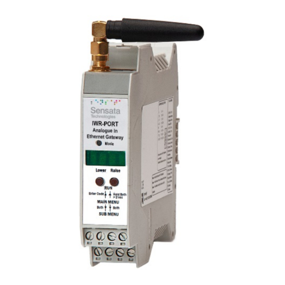
IWR-PORT
UTILITY OPERATING MANUAL
24 V AC or DC POWERED
with 128 channels
Cynergy3 Components Ltd
7 Cobham Road, Ferndown Industrial Estate, Wimborne
Dorset BH21 7PE, United Kingdom
Tel: +44(0)1202 897969, email: sales@cynergy3.com
www.cynergy3.com
Page 1
Advertisement
Table of Contents

Summary of Contents for Sensata IWR-PORT Series
- Page 1 This document may not be reproduced in any way without the prior written permission of the company. Cynergy3 Components Ltd 7 Cobham Road, Ferndown Industrial Estate, Wimborne Dorset BH21 7PE, United Kingdom Tel: +44(0)1202 897969, email: sales@cynergy3.com www.cynergy3.com Page 1 opyright © 2021 Sensata Technologies, Inc.
-
Page 2: Table Of Contents
Age Select (20.AGE age) ____________________________________________ 18 6.16 Led Control (21.LED led) ____________________________________________ 19 6.17 Restore Defaults (22.DEFAULTS) _____________________________________ 19 6.18 Modbus 32 bit float format (23.ENDIAN type) ___________________________ 19 6.19 AUTOSCALE (24.AUTOSCALE auto) __________________________________ 20 Page 2 opyright © 2021 Sensata Technologies, Inc. - Page 3 Writing Output Values _______________________________________________ 32 10. INSTALLATION __________________________________________________ 36 11. TROUBLESHOOTING ____________________________________________ 37 11.1 Incorrect Reading _________________________________________________ 37 11.2 Sensor Failure ____________________________________________________ 37 12. CERTIFICATIONS ________________________________________________ 38 13. SPECIFICATIONS (@ 25°C) ________________________________________ 40 Page 3 opyright © 2021 Sensata Technologies, Inc.
-
Page 4: Introduction
RS232/485 or Ethernet communications port. Isolation Details The IWR-Port has full 2 port isolation of 1000 V between the Output Stage and Power Supply for functional reasons. Page 4 opyright © 2021 Sensata Technologies, Inc. -
Page 5: Unpacking
QUICKSTART GUIDE There are many ways the IWR-Port can be used, here Sensata shows QUICKSTART examples of three different systems. Example 1 IWR-Port receives values from 8 IWTT thermocouple wireless transmitters and provides this information to an Ethernet network using a MODBUS TCP protocol. -
Page 6: Example 3
Measure the age of a reading in minutes by following the procedure in section 6.15. Exit the main menu by holding both buttons until OK is displayed. Calculate the registers to read by referring to section 9.1. Page 6 opyright © 2021 Sensata Technologies, Inc. -
Page 7: Connections
10 and 12. Antenna Ground Serial RS232 Receive or RS485 A RS232 Transmit or RS485 B 16-36 V dc / 16-32 V 0-10 V 0(4)-20 mA - ve Voltage Current OUTPUT Page 7 opyright © 2021 Sensata Technologies, Inc. -
Page 8: Configuring The Iwr-Port
1 1 0 0 6006 1 1 0 1 600E 1 1 1 0 6007 1 1 1 1 600F If the radio stops receiving data, a watchdog timer will reset it after 1 minute. Page 8 opyright © 2021 Sensata Technologies, Inc. -
Page 9: Calibrating The Iwr-Port
To access the sub-menu of one of the main menu options, use raise or lower to cycle to the option required then push and release both buttons. Change the parameter as required. To return to the main menu, push and release both buttons. Page 9 opyright © 2021 Sensata Technologies, Inc. -
Page 10: Output Span And Output Zero (1. Out Span And 2. Out Zero)
For example, if the span is 50% and zero is 20%, output switches on below 50% and off again above 70%. Example: To change the scaling of channel 3 parameter 2, from 0 - 100 to 4 - 20: Page 10 opyright © 2021 Sensata Technologies, Inc. -
Page 11: View Display Scaling Values (6.View Dsv)
The outputs of Isoslice units can also represent any parameter within the system. This is done using a link table, which links the outputs to the parameters (usually of input devices) they must represent. Page 11 opyright © 2021 Sensata Technologies, Inc. - Page 12 Channel 3 is an Isoslice-8 with 4 analog outputs, parameters 1 to 4. To make the IWR-Port output 1 follow Isoslice-2 input 1 and make output 1 on the Isoslice-8 follow input 2 of the Isoslice-2 Page 12 opyright © 2021 Sensata Technologies, Inc.
-
Page 13: View Link Table (9.View Link)
Go to main menu item 10. BURNOUT Cc Pp where c and p show the channel and parameter of the output that needs its burnout level to be changed or the input channel Page 13 opyright © 2021 Sensata Technologies, Inc. -
Page 14: View Burnout (13.View Burnout)
This shows that if this is an input, its data will become invalid if it is older than 30 seconds (or minutes depending on the AGE parameter selected, see section 6.15). e.g. for channel 3: Page 14 opyright © 2021 Sensata Technologies, Inc. -
Page 15: Serial Protocol (14.Modbus Type)
8 data bits, no parity, 1 stop bit (default) 8 data bits, no parity, 2 stop bits 8 data bits, odd parity, 1 stop bit 8 data bits, even parity, 1 stop bit Page 15 opyright © 2021 Sensata Technologies, Inc. -
Page 16: Character Timeout (18.Ch Time)
LINK to see an LED flash each time data is received. select this to see the led flash every 3 seconds (default) BEAT select this to see the led flash when a wireless transmission is received LINK Page 16 opyright © 2021 Sensata Technologies, Inc. -
Page 17: Restore Defaults (22.Defaults)
When channel 1, parameter 1 is viewed on the screen, 250 will be shown Modbus register Value Reason 40001 is 16-bit unsigned integer data of channel 1 parameter 1. 40001 32759 Halfway between 3869 and 61650 Page 17 opyright © 2021 Sensata Technologies, Inc. -
Page 18: Isoslice Bus
If the IWR-Port has an output fitted, the IWR-Port will configure itself to be channel 1, leaving channels 2 to 128 available for external transmitters or isoslice units. Channels are allocated to wireless devices and Isoslice units within the system, the channels must not be duplicated. Page 18 opyright © 2021 Sensata Technologies, Inc. -
Page 19: Serial Data Options
Default XPort settings are: DHCP is enabled, so an IP address is obtained automatically • The remote port is 502 (local port on the XPort) • The baud rate is 57600 • Page 19 opyright © 2021 Sensata Technologies, Inc. - Page 20 (169.x.x.x). This means that the IP address has not yet been assigned by the router. Click Search again, until the IP address is shown in black. Click on the Web Configuration tab, then click on the green arrow. Page 20 opyright © 2021 Sensata Technologies, Inc.
- Page 21 A connection screen will appear. Leave the Username and Password blank and click OK. Navigate to the Network section. In the main window where it says, IP Configuration select "Use the following IP configuration:" Page 21 opyright © 2021 Sensata Technologies, Inc.
- Page 22 Click Apply Settings on the left. Wait for it to reboot. It will now be possible to connect to the static IP address on port 502 with a SCADA system or Modbus test program. Page 22 opyright © 2021 Sensata Technologies, Inc.
-
Page 23: Accessing The Iwr-Port Data
0xFFF3: The input value is currently unavailable. 0xFFF4: The input span value is too close to the (saved) input zero value 0xFFF5: The input zero value is too close to the (saved) input span value Page 23 opyright © 2021 Sensata Technologies, Inc. - Page 24 Number of transmissions * 1024 For other IWT transmitters, P5 to P8 are available if bit 4 in the device type is set P7 Update rate Time (sec) P7 Update rate Time (sec) Page 24 opyright © 2021 Sensata Technologies, Inc.
- Page 25 {((13398 – 3869) / 57781) x (150 - -20)} + -20 = 8.0357 The value read from register 41281 is 0x4100 and 41282 is 0x922B Most significant word is first so 0x4100922B converts to 8.0357 Page 25 opyright © 2021 Sensata Technologies, Inc.
-
Page 26: Reading Scaling And Other Values
Reading 16-bit Zero Scaling Point Values: To calculate the 16-bit zero-point registers offset please refer to the IWR-Port Modbus register table (128 channel, 8 parameters). Convert the resulting signed integers as shown above. Page 26 opyright © 2021 Sensata Technologies, Inc. - Page 27 Bits 9:3 are 100 0111 = 0x47 = 71 which is channel 72 (because 0 to 127 represents channels 1 to 128) So, an output that is linked to decimal value 572 would be following channel 72, parameter 5. Page 27 opyright © 2021 Sensata Technologies, Inc.
-
Page 28: Writing Output Values
• 16-bit data values of analog or digital outputs • 16-bit span point scaling values if they are unlocked (see below) • 16-bit zero-point scaling values if they are unlocked (see below) Page 28 opyright © 2021 Sensata Technologies, Inc. - Page 29 They will only be changed by the IWR-Port if the Scaling values are unlocked, by first writing 0x0000 to register 48000 The scaling value must fall in the range of –999 to 9999 For positive numbers convert to hexadecimal e.g. 1000 converts to 0x03E8 Page 29 opyright © 2021 Sensata Technologies, Inc.
- Page 30 The parameter being followed is the bottom 3 bits of the link value (bits 2,1,0). The channel being followed is always bits 9,8,7,6,5,4,3. If an output needs to follow channel 63, parameter 2: Page 30 opyright © 2021 Sensata Technologies, Inc.
- Page 31 The next 7 bits for channel 63 are 011 1110 (which is the binary for 63 - 1, because 0 to 127 represents channels 1 to 128). So, the final number is 011 1110 001 = 01 1111 0001 = 0x1F1 = 497 Page 31 opyright © 2021 Sensata Technologies, Inc.
- Page 32 16 seconds is 0x0010 in hexadecimal Therefore, write 0x0010 to register 46658. They will only be changed by the IWR-Port if the Link values are unlocked, by first writing 0x0000 to register 48000 Page 32 opyright © 2021 Sensata Technologies, Inc.
-
Page 33: 10. Installation
Low burnout indication on an output E 15 Timeout Error: An input device value has timed out. E 16 Burnout Error: Check wiring connections of RTD or TC on an input. High burnout indication on an output Page 33 opyright © 2021 Sensata Technologies, Inc. -
Page 34: 11.1 Incorrect Reading
In this equipment, the antenna supplied is a PCB antenna and an alternative antenna must not be used. Caution: To satisfy FCC RF Exposure requirements for mobile and base station transmission devices, a separation distance of 20cm or more should be maintained Page 34 opyright © 2021 Sensata Technologies, Inc. - Page 35 Health EN 300 328 V2.1.1 / EN 62479:2010 (3.1(a)) EN 301 489-1 V2.1.1 (3.1(b)) EN 301 489-1 V2.2.0 EN 301 489-17 V3.1.1 EN 301 489-17 V3.2.0 Radio EN 300 328 V2.1.1 (3.2) Page 35 opyright © 2021 Sensata Technologies, Inc.
-
Page 36: Specifications (@ 25°C)
Buyers are authorized to use Sensata data sheets with the Sensata component(s) identified in each particular data sheet. HOWEVER, NO Cynergy3 Components Ltd. OTHER LICENSE, EXPRESS OR IMPLIED, BY ESTOPPEL OR OTHERWISE TO ANY OTHER SENSATA INTELLECTUAL PROPERTY RIGHT, AND NO LICENSE TO ANY THIRD PARTY TECHNOLOGY OR INTELLECTUAL PROPERTY RIGHT, IS GRANTED HEREIN.
Need help?
Do you have a question about the IWR-PORT Series and is the answer not in the manual?
Questions and answers