Table of Contents
Advertisement
Quick Links
Electric Druid FilterFX Construction Guide
Electric Druid FilterFX Project
Overview
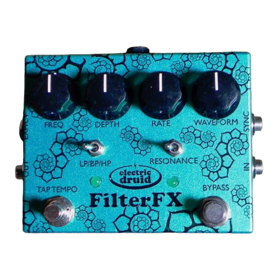
The FilterFX project uses the Druid STOMPLFO to control a 12dB/oct state variable filter. A state
variable filter is chosen because this filter design offers highpass, bandpass, and lowpass outputs
Page 1
www.electricdruid.net
1
3
3
3
3
3
4
4
4
4
4
4
4
5
5
5
5
6
7
7
8
8
9
10
10
10
10
10
10
11
11
11
11
11
11
Advertisement
Table of Contents

Related Manuals for Electric Druid FilterFX Project

Summary of Contents for Electric Druid FilterFX Project
-
Page 1: Table Of Contents
Adding CV inputs Adding further expression pedal inputs Overview The FilterFX project uses the Druid STOMPLFO to control a 12dB/oct state variable filter. A state variable filter is chosen because this filter design offers highpass, bandpass, and lowpass outputs Page 1... - Page 2 Electric Druid FilterFX Construction Guide www.electricdruid.net which gives us the greatest range of different effects. The LFO offers eight waveforms, including two random waveforms. Furthermore, the PCB provides for addition of an expression pedal to allow the filter to be used like a wah pedal (but don’t expect a replacement for your Clyde McCoy - this is a whole different...
-
Page 3: Build Instructions
“Done?” column on the far right. If you hold the PCB with the “FilterFX” title and “electric druid” logo the right way up, you’ll see that the board is shaped like a “T”. The top bar of the T has the Sync Input circuit, the vactrols, and the StompLFO chip. -
Page 4: Cup Of Tea And Soldering Check
There are only three of these, but you need to watch the polarity. • 47u capacitor x 2 - these are next to the two vactrols. • 100u capacitor - top left, just left of the electric druid logo Page 4... -
Page 5: Vactrols
The board is held in place by the pots and switches. You can download the FilterFX drilling template from the Electric Druid website. Note that the power input jack is a very tight fit if placed above the PCB as shown on the drilling template. -
Page 6: Install Ics
Electric Druid FilterFX Construction Guide www.electricdruid.net the back of the pots, to a piece of cardboard stuck between the board and the pots. My current favourite solution is to cut a piece of stiff overhead transparency plastic and slide it between the PCB and the pots. -
Page 7: Off-Board Wiring
Electric Druid FilterFX Construction Guide www.electricdruid.net Off-board wiring The off-board wiring for the FilterFX is fairly complex - take your time and break it up into sections. In fact, you don’t even have to do it all if you don’t want to, but we’ll come to that in a moment. -
Page 8: Optional Expression Pedal / Cv Input
Electric Druid FilterFX Construction Guide www.electricdruid.net Optional Expression pedal / CV input The optional Expression/CV input allows you to connect an expression pedal or CV source to replace the Frequency control of the filter. A stereo/TRS jack with normally closed contacts should be used. -
Page 9: Bill Of Materials
Electric Druid FilterFX Construction Guide www.electricdruid.net Bill of Materials Order Description Value Quantity Done? Polarity Protection Diode 1N5817 Signal Diode 1N4148 1% Metal film resistor 1% Metal film resistor 220R R16, R17, R18 1% Metal film resistor 470R 1% Metal film resistor... -
Page 10: Offboard Components
Electric Druid FilterFX Construction Guide www.electricdruid.net Offboard components Note that the BOM above doesn’t include offboard components. These are a matter of taste, but the basics are listed below. • Enclosure, PCB fits Hammond 1590BB or Eddystone 29830PSLA • Mono 1/4”/6.35mm Input jack •... -
Page 11: Op-Amps
Ideas for potential upgrades or customizations Adding CV inputs Since the Electric Druid STOMPLFO chip operates using 0-5V control voltages like many other Druid chips, it is possible to add CV control of the Offset(Frequency), Rate, Depth, or Waveform controls.
Need help?
Do you have a question about the FilterFX Project and is the answer not in the manual?
Questions and answers