
Subscribe to Our Youtube Channel
Summary of Contents for Nogueira VFN-9000
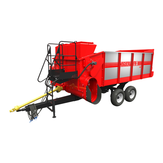
- Page 1 Feeder Wagon/Vagón Forrajero VFN-9000 INSTRUCTIONS MANUAL MANUAL DE INSTRUCCIONES NOGUEIRA Esencial en el campo Essential in the field...
-
Page 3: 1- Introduction
This information is extremely important to identify your machine, in cases when you need technical support or replacement parts. Nogueira S/A is always at your disposal to answer any questions or doubts and supply efficient and permanent technical support. The images displayed in this manual are only for illustrative purposes. Thus to facilitate your viewing, the images show cutaway or the safety shielding removed to display it more clearly. -
Page 4: Table Of Contents
Contents Introduction Safety Measures 2.1- Safety adhesive labels Forage Wagon presentation 3.1- Components identification 3.2- Operation 3.3- Technical specifications Forage Wagon setup and coupling 4.1- Assembly at receiving 4.2- Tractor head coupling 4.3- Cardan size adjustment 4.4- Checking the work angle Operation 5.1- Side discharge... - Page 5 Wrenches size table 10.2- Torque table Technical Assistance 11.1- Wagon series number 11.2- Warranty Term 11.3- Technical Delivery Voucher Note: NOGUEIRA Máquinas Agrícolas Ltda., aim is the constant update and improvement of its products, keeping itself the right of introduce changes without...
-
Page 6: 2- Safety Measures
2- Safety Measures Also follow the recommendations of your tractor’s Manual for a safety and efficient operation When reading the instructions manual Note: It means that an operational or safety detail will be presented Warning: It means that your life or parts of your body will be in danger. Pay attention to this symbol. - Page 7 Transporting on roads and streets Note: Wagon transport with the tractor must not be done on roads and streets. Such practice must be limited to inside the farm properties and rural zones. Refer to the traffic department for the regulations and laws in force in your region about the possibility or not of the transporting the machine with the tractor on certain parts of the roads, avoiding serious troubles.
- Page 8 Note: To transport the wagon, it is also need to bend and lock the lateral unloader chute (1), according to described below: 1- Remove the rear lock pin (2). 2- Bend the chute (1). 3- Install the front lock pin (3).
-
Page 9: Safety Adhesive Labels
2.1- Safety adhesive labels Turn off the tractor and remove the key Read the instruction manual before from the ignition before performing any turning on the machine. Pay close maintenance, adjustment, lubrication, attention to all the operating and safety cleaning jobs etc., on the machine. recommendations, in order to avoid any Thereby you will avoid any accidental unexpected accidents that may occur... - Page 10 2.1- Safety adhesive labels Keep your distance and never place your h a n d s n e a r t h e m o v i n g h e l i x t r a n s p o r t e r , a s contact can cause a Keep away from the articulating area, serious accident.
-
Page 11: 3- Forage Wagon Presentation
3- Forage Wagon presentation 3.1- Components identification 1- Coupling terminal 7- TANDEN wheel assembly 2- Head 8- Unrolling device 3- Stand jack 9- Conveyor 4- Full plating 10- Side outlet chute 5- Compartment of the driving system of 11- Rear outlet door the top unrolling device 6- Driving cardan... - Page 12 13- All components driving gear, in case of forage side unloading 14- All components driving gear, in case of forage rear unloading 15- Auger driving gear 16- Moto-reducer (it drives the conveyor - 9) 17- Gearbox (it drives the unroalling devices - 8)
-
Page 13: Operation
3.2- Operation Note: Whenever the terms ¨left¨ and ¨right¨ are used, it is considered the tractor’s operating cab as reference point Forage wagon is an equipment addressed to silage transport and also to carrying out unloading of silage in the through or silo. Its project aims quickness and efficiency in such applications. -
Page 14: Technical Specifications
3.3- Technical specifications Total height (A) ..................... 2.580 mm Total width (L1) ..................... 2.500 mm Width for transport (L2) ..................2.200 mm Chute height ......................750 mm Total length (C) ..................... -
Page 16: 4- Forage Wagon Setup And Coupling
4- Forage Wagon setup and coupling 4.1- Assembly at receiving In normal conditions, the wagon is transported with the head (1) assembled. However, if because of technical reasons you have to remove it, assemble it according to instructions below: Note: Coupling should be done on a flat and even place. -
Page 17: Tractor Head Coupling
4.2- Tractor head coupling Note: Coupling should be done on a flat and even place To couple the head to the tractor, follow the instructions below: a) Approximate the tractor aligning the draw-bar (1) with the coupling terminal (2) of the wagon. NOTE: Tractor draw-bar must have head (according to illustrated), preventing the wagon from raising up. -
Page 18: Cardan Size Adjustment
4.3- Cardan size adjustment At the first coupling, check whether the cardan shaft is with the proper length. For that, follow the instructions below: Removing the cardan protecting shield a) Uncouple the cardan shaft from the wagon. b) Follow the instructions of the item ¨Cardan shaft Cardan shaft with protection shield maintenance¨... -
Page 19: Checking The Work Angle
4.4- Checking the work angle The angle 0º is the center line of the tractor. The most angle allowed to the cardan, when it is being driven by the TDP, is 15º. In case it exceeds this value (example: maneuvers), turn off the PTO. -
Page 20: 5- Operation
5- Operation 5.1- Side discharge: A- Side discharge Forage Wagon leaves the factory with the side discharge, what allows the forage discharge by the auger. Move the tractor at a speed compatible with the discharge flow rate for even distribution. Observe belt behavior and adjust speed by varying power take-off speed. -
Page 21: Rear Discharge
5.2- Rear discharge It is a configuration which allows the product unloading in underground silos or other places with such purpose. Rear discharge settings: a) Remove the screw (1) from the gears (2); b) Remove the screw (3) from the gears (4); c Install one of these screws on the gear (5). -
Page 22: Pto Speed
5.2- PTO speed During the operation, the PTO speed should never exceed 540 rpm, in order to prevent forage spillage (see picture in the next page). There are four ways to find out the engine speed that generates such values in the PTO: Check for a possible indication in the tachometer (rpm counter) of the tractor. -
Page 23: Orientations About Discharge Flow
5.3- Orientations about discharge flow Basically, there are two ways to control the wagon frontal unloading flow: 1- Varying the PTO speed which controls the speed of the conveying chain. 2- Varying the tractor moving speed. For example, if the conveyor speed is much high in relation to the auger speed, there can be material building up in the outlet nozzle as well as irregular distribution. -
Page 24: 6- Tanden Wheels System
6.3- Tanden wheels system The Forage Wagon VFN-9000 is equipped with the Tanden wheels system with independent oscillation on the four wheels, allowing them to be always in uniform contact with the ground and following the ground irregularities. -
Page 25: 7- Maintenance Instructions
7- Maintenance instructions 7.1- Grease lubrication points Point Period Recommended grease Coupling terminal of the 50 work hours or weekly Lithium (Li) Class 2 base grease header (1) Stand-jack (2) 50 work hours or weekly Lithium (Li) Class 2 base grease * Wheel hubs End of each harvest Lithium (Li) Class 2 base grease... - Page 26 Notes: 1- Use a grease pump to lubricate the points 1, 2, 4 and 5. Grease point 3 with a brush. 2- Lubricate it right after a work period, while the machine is warm, because this way the grease flows better between the mobile parts.
- Page 27 Disassembling the wheels hubs (1) for lubrication a) Lift the Tanden wheel with a jack and support the wagon structure on stands, on safe points. b) Remove the cover (2) using a screw-driver. c) Remove the cotter pin (3), the nut (4) and the washer (5).
-
Page 28: Drive Chains Tension Adjustment
7.2- Drive chains tension adjustment Check the chains tension every 50 work hours or weekly, pressing them on the point indicated by the arrow. Chain play: Chains (A) and (D): 0,5 to 1,5 cm. Chain (B): 1 to 2 cm. Chain (C): Maximum 1 cm. - Page 29 Drive chains lubrication Keep the chains (previous page) clean. Whenever there is need, wash them with kerosene or diesel oil and a brush. Following, dry them with compressed air or natural flowing off. Apply a thin coat of oil proper for chains as MAXLUB ND-03 Bardahl. If available, use a lubricant special for chains (grease in spray).
-
Page 30: Conveying Chains Tension Adjustment
7.3- Conveying chains tension adjustment Tension check Conveying chains (1) should be properly tensioned. Check the tension on the central chain, at an intermediate point in the rear part of the wagon - see picture bellow. For that, pull the chain fully down in this point, removing the play. Rear lower view The scheme below better illustrates the deflection: The ¨X¨... - Page 31 Tension adjustment This adjustment is carried through the tension spindles (2). For that, release the counter-nuts (3) and turn the nuts (4) clockwise. NOTE: Evenly adjust the three tension spindle. To make sure the spindles are evenly adjusted, measure the distance (A) between the shaft (5) and the beam (6).
-
Page 32: Level Check And/Or Oil Replacement Of The Transmission Box And The Reducer
7.4- Level check and/or oil replacement of the transmission box and the reducer Oil capacity Transmission box = liters. 2- Reducer = Fill it up to the drain plug (3). Level check Check every 50 work hours or weekly and fill it up if there is need. - Page 33 Recommended oils Fill the gearbox and the reducer with one of the oils from the table below, according to the environment temperature: RECOMMENDED OIL...
-
Page 34: Cardan Schaft Maintenance
7.5- Cardan shaft maintenance Lubricate the drive shaft tube and its square bar section (1) each 50 working hours or weekly. Follow the steps: A) By having the cardan uncoupled, press the three locks simultaneously (2) and force the ´skirt´ (3) down. Repeat the same procedure with the ´skirt´... -
Page 35: Wagon Floor Preservation
7.6- Wagon floor preservation Every 6 months, apply a thin coat of linseed oil on the wagon wooden floor. 7.7- Tires pressure checking The correct tire pressure is basic for a long useful lifetime. Check the tires pressure every 50 work hours or weekly. In case there is need, adjust their pressure with the tires cold, according to table below. -
Page 36: 8- Forage Wagon Preservation
8- Forage Wagon VFN- 9000 preservation Daily preservation is as important as the machine preventive maintenance. Such care basically consists of sheltering the Forage Wagon VFN- 9000 from the weather and protecting it against the corrosive effect of some products. Follow the instructions bellow to assure a long useful lifetime to your equipment: Remove all product waste that remained inside the wagon. -
Page 37: 9- Troubleshooting
9- Troubleshooting Problem Causes Solutions Material building up in the Excessive conveyor speed Reduce the conveyor discharge chute speed, reducing the TDP speed Low amount of material Low conveyor speed Increase the conveyor coming out by the speed, increasing the TDP discharge chute speed Irregular discharge... -
Page 38: 10- Additional Information
10 Additional Information Key Gauge Table .2 - Torque Table N.m Torque Unit... -
Page 39: 11- Technical Assistance
Technical Assistance, always let us know the series and model of your Forage Wagon. Located on the identification plate. 2- Whenever replacing parts, always use Nogueira Genuine spare parts are made according to the drawing, materials and specifications with rigid quality control. - Page 43 En ninguma hipótesis, utilice la máquina sin las respectivas protecciones. La reproducción de este manual no es permitida sin la previa autorización por escrito de Nogueira Indústria e Comércio de Implementos e Máquinas Agrícolas S.A.
- Page 44 Índice Introcucción Medidas de seguridad 2.1- Adhesivos de seguridad Presentación del vagón forragero 3.1- Identificación de los componentes 3.2- Principio de funcionamiento 3.3- Especificaciones técnicas Preparación y enganche del Preparador y Repartidor 4.1- Ensamble tras recibir 4.2- Acoplamiento de la cabeza de empalme al tractor 4.3- Ajuste del largo del eje de toma de fuerza 4.4-...
- Page 45 Número de Serie del Vagón 11.2- Término de garantia 11.3- Comprobante de Entrega Técnica Nota: NOGUEIRA Máquinas Agrícolas, tiene como objectivo la constante actualización y perfeccionamiento de sus productos y se reserva el derecho de variar sus piezas y accesorios sin previo aviso.
-
Page 46: 2- Medidas De Seguridad
2- Medidas de seguridad Observe también las recomendaciones del Manual de su tractor, para una operación segura y eficaz. Al leer el Manual de instrucciones Nota: Significa que se presentará un detalle, que puede ser de operación o de seguridad. Atención: Significa que su vida o alguna parte de su cuerpo pueden estar en peligro. - Page 47 Transporte en rutas y vias públicas Notas: El transporte de la máquina con el tractor no debe ser realizado en vias públicas y autopistas. Esta práctica debe limitarse para dentro de las propiedades y zonas rurales. Consulte el departamento de tránsito sobre las leyes vigentes en su región, sobre la posibilidad de transportar la máquina con el tractor en carreteras, evitando asi contratiempos.
- Page 48 Nota: Para transportar la maquina, es necesario también doblar e inmobilizar la salida (1) de descarga lateral, según se describe a continuación. 1- Quite el perno de inmobilización trasero (2). 2- Doble la salida (1). 3- Instale el perno de inmobilización delantero (3).
-
Page 49: Adhesivos De Seguridad
2.1- Adhesivos de seguridad Lea el manual de instrucciones antes de Apague el tractor y retire la llave del encender la máquina. Manteniéndose arranque antes de realizar servicios de atento y respeta ndo todas las mantenimiento, regulado, lubricación, recomendaciones de uso y seguridad, limpieza etc., en la máquina. - Page 50 2.1- Adhesivos de seguridad Mantenga distancia y nunca acerque las manos a las roscas en movimiento, el c o n t a c t o p u e d e causar un accidente Manténgase fuera del área de grave. articulación, entre la máquina y el tractor. El movimiento lateral de la máquina puede alcanzarlo, provocando un accidente.
-
Page 51: Identificación De Los Componentes
3- Presentación del Vagón VFN-9000 3.1- Identificación de los componentes 1- Barra de remolque 7- Conjunto rodado doble 2- Cabeza de empalme 8- Descompactador 3- Pata de soporte 9- Transportador 4- Revestimento 10- Salida de descarga lateral 5 - A l o j a m i e n t o d e l s i s t e m a d e... - Page 52 13- Enganaje de mando de todos los componentes, cuando se realiza la descarga lateral del forrage. 14- Engranaje de mando de todos los componentes, cuando se realiza la descarga trasera del forrage 15- Engranaje de mando del sinfin 16- Motor reductor (acciona el transportador - 9) 17- Caja de transmisión (acciona los descompactadores - 8)
-
Page 53: Principio De Funcionamiento
3.2- Principio de funcionamiento Nota: Siempre que las palabras ¨izquierdo¨ y ¨derecho¨ sean empleadas, considere como referencia el asiento del operador del tractor. El Vagón es un equipo que se destina al transporte y también a realizar la descarga de forrage en la batea o en el silo. -
Page 54: Especificaciones Técnicas
3.3- Especificaciones técnicas Altura total (A) ...................... 2.580 mm Ancho total (L1) ....................2.500 mm Ancho para transporte (L2) .................. 2.200 mm Cilindro de la boquilla de descarga ................. 750 mm Largo total (C) .............. -
Page 56: Ensamble Tras Recibir
4- Preparación y enganche del Vagón VFN- 9000 4.1- Ensamble tras recibir Bajo condiciones normales de la maquina será transportado con la barra de remolque (1) ensamblada. Sin embrago, por razones técnicas la misma haya sido retirada, el ensamble se hará... -
Page 57: Acoplamiento De La Cabeza De Empalme Al Tractor
4.2- Acoplamiento de la cabeza de empalme al tractor Nota: El enganche debe ser hecho en local plano. Para enganchar la cabeza de empalme al tractor siga las instrucciones a seguir: a) Aproxime el tractor, alineando la barra de tiro (1) con la cabeza de empalme (2) del la maquina. -
Page 58: Ajuste Del Largo Del Eje De Toma De Fuerza
4.3- Ajuste del largo del eje de toma de fuerza Al realizar el primer acoplamiento, compruebe si el eje de toma de fuerza posee la extensión adecuada. Para ello, siga las instrucciones a continuación: Remoción de las protecciones del eje de toma de fuerza a) Desacople el eje del vagón. -
Page 59: Comprobación Del Ángulo De Trabajo
4.4- Comprobación del ángulo de trabajo El ángulo 0º es la línea de centro del tractor. El ángulo máximo permitido para el eje, cuando está siendo accionado por la TDF es de 15º. Si sobrepasa este valor (ejemplo: maniobras), apague la toma de fuerza. Nota: Con la TDF desacoplada el ángulo máximo del eje en maniobras puede alcanzar 30º... -
Page 60: 5- Operación
5- Operación 5.1- Descarga lateral (sinfin) El Preparador y Repartidor de Ensilaje sale de la planta con descarga lateral, lo que permite la descarga del producto por el sinfin. Utilice éste recurso para descarga en cuencos de encierras. Desplace el tractor a una velocidad compatible con el caudal de descarga, de manera a obtener una distribución uniforme de forrage. -
Page 61: Descarga Trasera
5.2- Descarga trasera Es una configuración especial, que permite la descarga del producto en silos subterráneos u otros locales con esa finalidad. Regulación para la descarga trasera: Quite el tornillo y el tornillo ‘ ' engr anaje ‘ ' ‘ ' del engranaje ‘... -
Page 62: Rotación De La Tdf 2
5.3- Rotación de la TDF Durante la operación, la rotación de la toma de fuerza nunca debe sobrepasar las 540 rpm, evitando así que se derrame forrage (vea la figura de la próxima página). Para saber cual es la rotación del motor que genera estos valores en la TDF, hay cuatro posibilidades: Verificar una posible indicación en el cuentarrevoluciones del tractor. -
Page 63: Orientaciones Sobre El Caudal De Descarga 2
5.4- Orientaciones sobre el caudal de descarga En resumen hay dos maneras de controlar el caudal de descarga frontal del vagón: 1-Variando la rotación de la TDF, la cual controla la velocidad de la cadena transportadora. 2- Variando la velocidad de desplazamiento del tractor. Si por ejemplo, la velocidad del transportador está... -
Page 64: 6- Sistema De Rodado Doble
6- Sistema de rodado doble El Vagón VFN-9000 está equipado con el sistema de rodado doble, con oscilación independiente en las cuatro ruedas, permitiendo que queden siempre en contacto uniforme con el suelo y acompañen las irregularidades del terreno. - Page 65 Notas: 1- Utilice un engrasador para lubricar los puntos 1, 2, 4 y 5. En el punto 3, hágalo con un pincel. 2- Lubrique tras un período de trabajo, mientras el equipo aún está caliente, pues de ésta manera la grasa penetrará...
-
Page 66: 7- Instrucciones De Mantenimiento
7- Instrucciones de mantenimiento 7.1- Puntos de lubricación con grasa Punto Período Grasa recomendada Barra de remolque de la 50 horas de trabajo o Grasa a base de Lítio (Li) Clase 2 cabeza de empalme (1) semanalmente 50 horas de trabajo o Pata de soporte (2) Grasa a base de Lítio (Li) Clase 2 semanalmente... - Page 67 Desmontaje de los cubos de rueda (1) para lubricación a) Alce las rudas con un gato y apoye el bastidor del Vagón sobre caballetes, en puntos seguros. b) Quite la tapa (2) con auxilio del destornillador. c) Quite el pasador doble (3), la tuerca (4) y la arandela (5).
-
Page 68: Ajuste De La Tensión De Las Cadenas De Accionamiento
7.2- Ajuste de la tensión de las cadenas de accionamiento Compruebe la tensión de las cadenas a cada 50 horas de trabajo o semanalmente, ejerciendo presión en el punto indicado por la flecha. Juego de las cadenas: Cadenas (A) y (D): 0,5 hasta 1,5 cm. Cadena (B): 1 hasta 2 cm. - Page 69 Lubricación de las cadenas de accionamiento Mantenga las cadenas (página anterior) limpias. Siempre que necesario, lávelas con un pincel y querosén o aceite diesel. A seguir, séquelas con aire comprimido o déjelas escurrir naturalmente. Aplique una ligera película de aceite especial para cadenas (consulte su proveedor de lubricantes).
-
Page 70: Ajuste De La Tensión De Las Cadenas Transportadoras
7.3- Ajuste de la tensión de las cadenas transportadoras Control de tensión Las cadenas transportadoras (1) deben estar correctamente tensadas. Compruebe la tensión en la cadena central, sobre un punto intermedio de la parte posterior del vagón - vea la figura a continuación. Para ello, tire la cadena totalmente hacia abajo en ese punto, eliminando el juego. - Page 71 Ajuste de tensión El ajuste es realizado por medio de los husos tensores (2). Para ello, afloje las tuercas (3) y gire las tuercas (4) para la derecha. OBS.: Realice un ajuste parejo en los tres husos de ajuste. Para asegurarse que los husos están ajustados correctamente, tome la distancia (A) entre el eje (5) y el travesaño (6).
-
Page 72: Comprobación Del Nivel Y/O Cambio De Aceite De La Caja De La Transmisión Y Del Reductor
7.4- Comprobación del nivel y/o cambio de aceite de la caja de la transmisión y del reductor Volumen de aceite Caja de transmisión = litro. 2- Reductor = Llenar hasta alcanzar el orificio del tapón de drenaje (3). Comprobación del nivel Compruebe a cada 50 horas trabajo o semanalmente y complete, si necesario. -
Page 73: Mantenimiento Del Eje De Toma De Fuerza
7.5- Mantenimiento del eje de toma de fuerza Lubrique a cada 50 horas de trabajo o semanalmente el tubo y la barra de sección cuadrada del cardan (1). Siga el procedimiento: A) Con el cardan desenganchado, presione simultáneamente las tres trabas (2) y forzar el “faldón” (3) hacia abajo. - Page 74 Aceites recomendados Llene la caja y el reductor con un tipo de aceite lubricante que conste en la tabla a continuación, según la temperatura ambiente: ACEITES RECOMENDADOS...
-
Page 75: Calibración De Los Neumáticos
7.6- Conservación del piso del Vagón A cada 6 meses, pase aceite de linaza en la madera del piso del Vagón de ensilage VFN- 9000. 7.7- Calibración de los neumáticos La calibración correcta de los neumáticos es fundamental para la conservación de los mismos. - Page 76 8- Conservación del Vagón VFN-9000 Tan importante cuanto el mantenimiento preventivo, es la conservación diaria del equipo. Este cuidado consiste básicamente en proteger el equipo de la intemperie y de los ataques corrosivos de algunos productos. Siga las siguientes recomendaciones con el fin de asegurar una larga vida útil a su equipo.
-
Page 77: 9- Diagnóstico Y Solución De Problemas
9- Diagnóstico y solución de problemas Anormalidad Causas Soluciones Acumulación de material en Velocidad elevada del Disminuir la velocidad del el bocal de descarga transportador transportador, reduciendo la rotación de la TDF Salida de poco material por Baja velocidad del Disminuir la velocidad del el bocal de descarga transportador... - Page 78 10 Informaciones Adicionales Tabla de Medidas de las Llaves .2 - Tabla de Par de Apriete Unidad de Par de Apriete en N.m...
- Page 79 11 - Asistencia Técnica 11.1- Número de Serie del Vagón El Vagón VFN-9000 es identificado con un número de serie, lo que permite mantener registros de eventuales cambios introducidos en los componentes y en las caracteristicas constructivas. El Número de Serie está grabado en una placa de datos (1) fijada en la parte de adelante, lado izquierdo del vagón.
- Page 84 05.201079 - Publicação 08/19 - Revisão NOGUEIRA Ind. Com. Impl. Máquinas Agrícolas S.A. Rua Fernando de Souza, 533 - Distrito Industrial CEP 13877-775 - Tel.: + 55 19 3638.1500 NOGUEIRA CNPJ: 08.510.974/0001-27 nogueira@nogueira.com.br www.nogueira.com.br Esencial en el campo Essential in the field...
Need help?
Do you have a question about the VFN-9000 and is the answer not in the manual?
Questions and answers