
Related Manuals for Elforlight HPG Series

Summary of Contents for Elforlight HPG Series
- Page 1 HPG Series Diode Pumped Solid State lasers Elforlight Ltd Nene House Drayton Way Daventry Northants NN11 8EA Tel +44 1327 300069: Fax +44 1455 552974 www.elforlight.com HPG Manual.docx 12/01/2018...
- Page 2 NOTICE Elforlight Ltd. has made every attempt to ensure that the information in this document is accurate and complete. Elforlight Ltd. assumes no liability for errors, or for any incidental, consequential, indirect or special damages, including, without limitation, loss of use, delays or lost profits or savings, arising from the use of this document, or the product which it accompanies.
-
Page 3: Table Of Contents
Contents Basic Operation Operation through RS232 To stop the Laser in normal operation To shut down the laser IN EMERGENCY SITUATION ONLY Front Panel Keyswitch Indicators Rear Panel Features System components and features Laser head Power supply Interlock Shutter Laser Safety Classification Emission Indicators... -
Page 4: Basic Operation
HPG Series Diode Pumped Solid State Laser 1. Basic Operation The HPG Series Lasers are microprocessor controlled, and designed for simple, user friendly operation from most PC type computers through the serial (RS232) port. Ensure that the Laser Head is connected correctly to the Power Supply by means of the umbilical cable supplied. -
Page 5: To Stop The Laser In Normal Operation
Turn the front panel key switch to the “On” position. By default, the laser starts up with parameters set as follows: * Control by RS232 mode * Interlock latch is reset (operation possible if external interlock contacts are closed) * Diode current(s) set to zero * Diode and oven temperatures controlling Shutter closed WAIT AT LEAST 5 MINUTES FOR THE SYSTEM TO REACH... -
Page 6: Front Panel
The full command structure for the laser is given in the appended programmer manual. The commands can, of course, be embedded into the user’s own software for control of the laser with other equipment. NOTE: TO PROTECT THE LASER CRYSTAL(S) THE LASER DIODE CURRENT IS RAMPED UP AND THEREFORE THERE IS A TIME DELAY BEFORE LASER OUTPUT IS OBSERVED AFTER A CURRENT DEMAND (RS232) OR A LASER ON COMMAND (RS232). -
Page 7: Indicators
2.2 Indicators Power (Green) Indicates that the system has mains power applied, the internal switch mode power supply is generating the correct voltages and the microprocessor is functioning. Emission (Yellow) Confirms that the laser is ready to lase or is lasing. This means that power is applied, the keyswitch is in the “On”... -
Page 8: Rear Panel
3. Rear Panel connections FIG 2. Rear Panel Mains input RS232 port Fibre optic port PZT connector User interface Umbilical connector External interlock connector 3.1 Features External interlock connect or The external interlock connector gives access to the laser system interlock chain. Contact closure is required between pins 1 and 3. -
Page 9: System Components And Features
RS 232 Connector 9 way D-socket, pins 2 and pin 5 through connected, pin 3 at PC to pin 8 at laser (see Fig 1). Connects to computer serial port. Umbilical connector to laser head. Takes 28 pin QM connector (umbilical cable supplied). Fibre optic port The pump laser diode light is fed to the laser head via a 3m armoured fibre optic cable (supplied). -
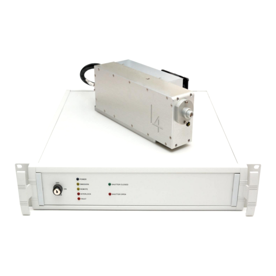
Page 10: Laser Head
Fig 3. The Laser Head Umbilical Laser Head Fibre optic input 4.2 Power supply Fig 4. and Fig 5. The power supply is housed in a 2U high 19” case. (Bench top mounting case optional). This case contains the switchmode power supply which delivers the required DC voltages, the microprocessor board, diode current control board, TEC and oven control board. -
Page 11: Interlock
Fig 4. The Power Supply (front view) Fig 5. The Power Supply (rear view) 4.3 Interlock The external interlock requires contact closure between pins 1 and 3 of the rear panel connector. The connector is supplied with these pins shorted out, but the link can be replaced with an external loop, for example to a door switch. -
Page 12: Shutter
5.1 Classification Elforlight HPG Series lasers are classified as class 4 lasers by the BS EN 60825-1:1994 and by the United States Center for Device and Radiological Health (CDRH). This designates potential danger of eye or skin damage by exposure to direct or scattered This means that they are considered in the most dangerous radiation. -
Page 13: Indicators
5.3 Indicators An emission indicator on the front panel of the power supply, duplicated on the laser head, indicates that laser emission is possible. 5.4 External interlock The FQ and FC series laser system is provided with an external interlock facility, which is available on the socket on the rear of the power supply. - Page 14 Click the Advanced button then open the drop down menu next to COM port number. Select COM20 from the list then click OK. Close all remaining open menus. Copy Laser.ht from the Elforlight supplied CD to your PC’s desktop. Double click on the Laser.ht icon to commence communication. HPG Manual.docx...
- Page 15 Appendix 2 RS232 Commands: Quick Start Guide. The laser system can respond to simple ASCII commands. To enter RS232 control mode, switch on the laser at the mains and turn the keyswitch to the "ON" position. The yellow led marked “Remote” on the front panel will be ON. RS232 Protocol 9600 baud, 1 start bit, 8 data bits, no parity, 1 stop bit no hardware handshaking, no software handshaking...
- Page 16 } Link together } Link together Shield Shield Do NOT connect to or link any other pins on the Laser end plug, as you may cause the laser to enter flash programming mode. Terminal Emulation The laser may be controlled simply by a dumb terminal emulator program outputting ASCII text on the RS232 port.
- Page 17 User Commands ALL<enter> Display laser system status FAULT FAULT<enter> Display cause of fault FAULT 0<enter> Clear fault condition If the red fault LED is lit on the front panel, use the FAULT command to find out the cause. To attempt to clear the fault, use the FAULT 0 command. FBMODE FBMODE<enter>...
- Page 18 IMON IMON<enter> Display current flowing through laser diode ILIM ILIM<enter> Display current limit for laser diode ILIM n pw<enter> Set current limit for laser diode. 0<=n<=10.0 pw = “******” This parameter is factory set and must not be changed by the user. INTLK INTLK<enter>...
- Page 19 SHUTTER Open, close, or query shutter status SHUTTER<enter> Query shutter status SHUTTER 0<enter> Close shutter SHUTTER 1<enter> Open shutter TEMP TEMP<enter> Show temp set points and monitor for active channels TEMP a<enter> Show temp set points and monitor for all channels TEMP b<enter>...
- Page 20 VER<enter> Display Firmware Version Figure 6. HyperTerminal example HPG Manual.docx 12/01/2018...
Need help?
Do you have a question about the HPG Series and is the answer not in the manual?
Questions and answers