Table of Contents
Advertisement
Quick Links
Advertisement
Table of Contents

Related Manuals for NetComm NRB-0206-02-01

Summary of Contents for NetComm NRB-0206-02-01
- Page 1 Quick Start Guide Smart Antenna Tool NRB-0206-02-01 Model: NRB-0206...
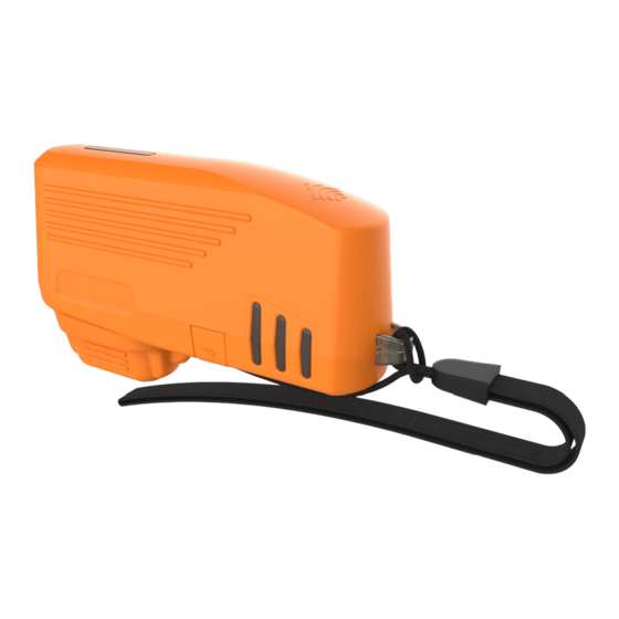
- Page 2 NetComm Wireless Smart Antenna Tool. The Smart Antenna Tool is a battery-powered tool which connects to the alignment port on the back of a NetComm Wireless Outdoor Unit, providing power and a wireless access point. The installer can then use a portable wireless device, such as a laptop or tablet, to connect to the Outdoor Unit to read signal strength data and align it in the optimal position.
-
Page 3: Package Contents
Smart Antenna Tool Package contents The NRB-0206-02-01 package includes: 1 x NRB-0206-02-01 Smart Antenna Tool 1 x Smart Antenna Tool pouch 1 x WiFi security card 1 x Quick Start Guide 1 x AC wall charger (5V/2A)* 1 x Micro USB to Type-A charge cable... -
Page 4: Device Overview
Device overview ITEM DESCRIPTION Connector Protects the connector from dust and moisture when the protective cap Smart Antenna Tool is not in use. Power button Push once to power the Smart Antenna Tool on. In approximately three (3) seconds the LEDs will illuminate. When turned on and not connected to the Outdoor Unit, the Smart Antenna Tool displays the remaining battery charge level. - Page 5 Smart Antenna Tool...
- Page 6 Charging the Smart Antenna Tool The included USB cable can be used to charge the Smart Antenna Tool. Connect the USB cable from the Micro USB port on the Smart Antenna Tool to the included AC wall charger or another 5V/2A power source for optimum charging speed. The LED indicators on the side of the Smart Antenna Tool light up and may flash depending on the remaining battery level.
-
Page 7: Led Indicators
Smart Antenna Tool LED Indicators WARNING: The LED indicators are designed to be bright so that they are visible outdoors. Do not view the LED indicators from close proximity or for long periods. The same LED indicators can have different meanings depending on the mode of operation which the Smart Antenna Tool is currently in. - Page 8 Compass Calibration mode - The Smart Antenna Tool contains an electronic compass which periodically requires calibration in order to provide the most accurate orientation possible. Calibrate the device at every start and recalibrate when all three LED indicators flash both red and green twice a second. To calibrate the device, first isolate it from any magnetic field or metal structures (for example vehicles, the antenna pole, power lines, etc.) and then rotate the unit fully through all three axes, see drawings below.
- Page 9 Smart Antenna Tool Normal operation mode – When the Smart Antenna Tool is connected to an Outdoor Unit and Power over Ethernet is also being supplied to the Outdoor Unit. This mode is used on an existing installation. LED 1 indicates the Ethernet connection status of the Outdoor Unit.
- Page 10 Using the Smart Antenna Tool to align an Outdoor Unit Before beginning to align an Outdoor Unit, press the Power button on the bottom of the Smart Antenna Tool and observe the battery level indicated by the LED indicators. Ensure that you have an adequate charge level for the installation. To align an Outdoor Unit: Prepare the Outdoor Unit as per the Installation Guide.
- Page 11 Smart Antenna Tool Power on the Smart Antenna Tool and calibrate the compass as described on page 8. Remove the protective cap from the Smart Antenna Tool’s connector then connect the Smart Antenna Tool to the alignment port of the Outdoor Unit as shown below.
- Page 12 Wait approximately 1 minute for the Outdoor Unit to go through its boot up process. WARNING: When the Smart Antenna Tool is connected to the Outdoor Unit, do not point the front panel of the Outdoor Unit directly at other people or yourself. Always maintain a separation distance of 8 inches between any part of your body and the front of the Outdoor Unit (the official FCC recommendation specifies 20cm separation).
- Page 13 Smart Antenna Tool THIS PAGE INTENTIONALLY LEFT BLANK.
-
Page 14: Safety And Regulatory Information
Safety & Regulatory Information... - Page 15 Smart Antenna Tool RF Exposure The NRB-0206-02-01 contains a transmitter and a receiver. When it is on, it receives and transmits RF energy. When you communicate with your device, the system handling your connection controls the power level at which your device transmits.
-
Page 16: Fcc Statement
FCC Statement FCC compliance Federal Communications Commission Notice (United States): Before a wireless device model is available for sale to the public, it must be tested and certified to the FCC that it does not exceed the limit established by the government-adopted requirement for safe exposure. - Page 17 Smart Antenna Tool However, there is no guarantee that interference will not occur in a particular installation. If this equipment does cause harmful interference to radio or television reception, which can be determined by turning the equipment off and on, the user is encouraged to try to correct the interference by one or more of the following measures: Reorient or relocate the receiving Outdoor Unit.
- Page 18 THIS PAGE INTENTIONALLY LEFT BLANK.
- Page 19 Smart Antenna Tool THIS PAGE INTENTIONALLY LEFT BLANK.
- Page 20 Safety and product care Please refer to the user guide for safety and product care information. NETCOMM WIRELESS LIMITED ABN 85 002 490 486 Head Office, 18-20 Orion Road Lane Cove, Sydney, NSW 2066, Australia +61 2 8205 3888 +61 2 9424 2010 sales@netcommwireless.com...
Need help?
Do you have a question about the NRB-0206-02-01 and is the answer not in the manual?
Questions and answers