Table of Contents
Advertisement
Quick Links
Advertisement
Table of Contents

Summary of Contents for Caribou MK3 Rel. 3
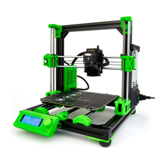
- Page 1 Caribou MK3 Rel. 3 Assembly Manual Version 1.20 11.09.2020...
- Page 3 INCIDENTAL OR CONSEQUENTIAL DAMAGES and assumes no responsibility or liability for any loss or damage suffered by any person as a result of the use or misuse of any of the provided information or product. Caribou Research & Development assumes or undertakes NO LIABILITY for any loss or damage suffered as a result of the use, misuse or reliance on the information and or product.
-
Page 4: Disclaimer
Building the printer will require physical dexterity and a good understanding of what you are doing. We have provided fully comprehensive build documentation to enable you to build your Caribou 3d Printer Kit in a safe manner. -
Page 5: Table Of Contents
Contents Disclaimer: ................................3 Thanks ................................. 7 Sources ............................... 7 General Notice ..............................9 List of tools ................................ 10 Assembly Instructions ............................11 xy-Frame ..............................11 5.1.1 Base frame Assembly ........................11 5.1.2 L-Bracket and Feet Installation ......................20 y-Axis Assembly ............................22 5.2.1 y-Rod Installation .......................... - Page 6 6.2.3 Bondtech Extruder Preparation ....................... 95 6.2.4 Installing the Fans and the PINDA probe ..................103 6.2.5 Installation of the Filament Sensor ....................105 6.2.6 Installing the x-Carriage......................... 107 Extruder Installation ..........................109 6.3.1 Stock Extruder ..........................109 6.3.1 Bondtech Extruder ......................... 109 x-Belt installation ...........................
- Page 7 Tools ............................... 177 x-Axis ............................... 178 A.1.6 Bondtech specific parts for x-Axis ....................179 A.1.7 Default Extruder specific parts for x-Axis ..................180 y-Axis ............................... 181 z-Axis ............................... 183 Extruder ..............................184 A.1.8 Bondtech Extruder ......................... 184 A.1.9 Default Extruder ..........................186 Length of Nylon filament and Techflex Tubes .....................
-
Page 8: Thanks
• Very special thanks to 3d-Gussner and Bernd Brinkert for their huge support and effort in providing and testing Caribou firmware. Thank you, Rebecca and Jason, from LDO Motors and Martin from Bondtech for the quality manufacturing and relationship. - Page 9 y-bearing holder the clamp mechanism is similar to one used on the x-axis. We like to mention that the first clamp • design with insert for the carriage for the bearings holders was done by Vecko Kojchevski https://www.thingiverse.com/thing:2930007 x-MotorHolder and X-Idler inspired by initial clamp design of Arnaud •...
-
Page 10: General Notice
3 GENERAL NOTICE Before you proceed with any of the construction steps, please do the following: 1. Make sure that the required parts (which are listed at the beginning of each chapter) are all present, correct and not damaged. If that isn't the case, please contact our support (support@caribou3d.com) and we will provide you with a replacement as quickly as possible. -
Page 11: List Of Tools
4 LIST OF TOOLS Necessary: ball-headed hex keys in sizes 2.5mm, 5mm, 6mm hex keys in sizes 1.5mm, 2mm ratchet with 5mm and 6mm hex bits pliers calipers (at least 162mm width) wrenches in sizes 7mm, 16mm phillips (PH1) and slotted (about 4-6mm wide) screwdriver scalpel or cutter knife scissors permanent marker (thin) -
Page 12: Assembly Instructions
5 ASSEMBLY INSTRUCTIONS 5.1 XY-FRAME 5.1.1 BASE FRAME ASSEMBLY ② ③ ④ ① ⑤ ⑥ ⑦ ⑧ ⑨ ⑩ ⑥ ① ② ⑦ L-bracket (4x) T-Nut (32x) ③ ⑧ Extrusion cover (4x) Misumi rubber feet (4x) ⑨ ④ M8 x 40mm hex socket Corner Brackets (4x) screw (4x) ⑤... - Page 13 Prepare four corner brackets in the following way: Insert a M6 x 12mm screw to one of the holes of the bracket. Screw a T-nut on the M6 x 12mm screw. Leave it loose. Top and side view of the bracket. Do the same for the second hole of the bracket.
- Page 14 Repeat the last two steps on the back of the frame. IMPORTANT: slide in 2x T-nuts in the front slot of the front extrusions. They will be used to attach the LCD. Insert the M8 x 40mm screws into the front x-axis.
- Page 15 Now use a right-angle ruler e.g. DIN 875/1 to press the extrusions flat on your build plate while tightening the M8 x 40mm screw. DON’T tighten too much! Do the same on the left side. Repeat the last two steps on the back of the frame.
- Page 16 Now loosen the 4x M8x40mm screws about 2-3mm. Each corner bracket should now sit flush with the end of the corresponding Y-extrusion. Prepare the extrusion covers. The middle part is too long to fit on the end of the extrusions due to clearance issues with the M8x40mm screws.
- Page 17 Now install the caps onto the ends of the two X-extrusions. The thickness of the cap is 2.8mm, which we will use to align the x-extrusions and the corner brackets. After pushing the caps, the corners of the frame should look like this. Reminder: Note that at this point the M8x40mm screws are loose.
- Page 18 Using a right-angle ruler to make sure that the two extrusions in one corner are aligned and that the extrusions are at a 90°angle in relation to each other. Now place the angle on the profiles. Now tighten the loose M6x12mm screw the corner bracket, fastening the bracket to the x-extrusion.
- Page 19 The following two steps are OPTIONAL: if you own calipers that are 300m long. Measure the distance between the two Y- extrusions at the front. This should be somewhere around 299.40 – 300.00mm. Now measure the rear part of the frame. The difference in length in comparison to the front should not exceed 0.1mm.
- Page 20 Tighten the four M8 x 40mm. Don’t overtighten them. This may bend the frame. Remover one of the end caps on the front and on the back of the frame Insert 6x T-nuts in upper slot of the front extrusion. Insert 8x -T-nuts in the upper slot of the...
-
Page 21: L-Bracket And Feet Installation
5.1.2 L-BRACKET AND FEET INSTALLATION ① ② ③ ④ ① ③ ② ④ L-bracket (4x) M6 x 20mm hex socket screw (4x) T-Nut (4x) Misumi rubber feet (4x) - Page 22 Flip the frame upside down. Insert 2x T-nuts into the (now) upper slots of each extrusion. For each corner, set a T-nut in the position as seen in the picture, and place an L- bracket over it. For each corner, place one of the rubber feet onto the bracket.
-
Page 23: Y-Axis Assembly
5.2 Y-AXIS ASSEMBLY 5.2.1 Y-ROD INSTALLATION ① ③ ② ④ ⑤ ⑥ ⑦ ① ⑤ ⑥ ② y-rod mount (4x) M3 hex nut (8x) ③ ⑦ y-rod mount cover (4x) M3 x 8mm hex socket screw (1x) ④ T-Nut (8x) M3 x 10mm hex socket screw (8x) - Page 24 Insert 2x M3 self-securing hex nuts into each Y-rod mount bottom. You may use pliers to do so. Using an M3x8mm screw, pull the nuts into their slots. Set the frame to be in the following position. Position the T-nuts in the extrusion as shown in the picture.
- Page 25 Use the y-alignment tool to make the rod parallel to the y-extrusions. Do this by firstly placing the tool at the top and then pushing the rod against it. Secondly slide the tool down the frame to the other side and push the rod against it again.
-
Page 26: Installation Of The Heatbed Carriage
5.2.2 INSTALLATION OF THE HEATBED CARRIAGE ② ① ④ ③ ⑥ ⑧ ⑦ ⑨ ⑩ ⑪ ⑤ ⑫ ⑬ ⑭ ⑮ ⑯ ⑰ ⑱ ⑲ ⑳ ① ⑫ ② ⑬ Y-carriage M3 nyloc nuts (9x) ⑭ ③ Superlube M3 washer (13x) ④... - Page 27 Immerse the 10 supplied bearings for about 20min in IPA. Take them out and let them dry for about 10-15min on a paper towel. Open the super lube tube and screw on the provided injector. Place a bearing on the injector and align the channels of the bearing with the slots on the injector.
- Page 28 Pay attention to the orientation of the bearings. The balls should be oriented in a 45° angle with respect to the top plane of the holder. Secure the bearing by pushing in a M3 hex on one side and screwing in a M3 x 18mm screw.
- Page 29 Don fasten the bearings holders yet. The holders should be able to move and rotate slightly. View from the side. View from top.
- Page 30 Carefully lift the installed y-rods and slide in the carriage. Pay attention to the direction. When viewed from behind the side with the two bearings has to be on the right. Slide the carriage back and forth so that the left (loose) rod can align. Now fasten the M6 x 12mm screws of the...
-
Page 31: Y-Motor Assembly
5.2.3 Y-MOTOR ASSEMBLY Attach the motor mount onto the motor, with the cables exiting towards the M6 holes on the back (don’t get confused by the picture). Use 4x M3 washers M3x10mm screws to attach the motor to the mount. Slide the toothed GT3 pulley onto the motor shaft. -
Page 32: Xy-Idler (Tensioner) Assembly
5.2.4 XY-IDLER (TENSIONER) ASSEMBLY Take the belt tensioner and insert the dowel pin until you can see about half a millimeter of the pin inside the tensioner. If you feel that the hole is too small, you may use a 3mm drill bit (by hand!) to widen the hole slightly. -
Page 33: Y-Idler And Y-Belt Installation
5.2.5 Y-IDLER AND Y-BELT INSTALLATION Attach the Y-belt tensioner mount to the front extrusion opposite to the motor in the orientation shown. Use two M6 x 12mm screws and the 2x T- nuts that we inserted into the extrusion in chapter 1. - Page 34 Pay attention to the orientation of the belt holder. The side with the fastened belt should face the side of the carriage with ONE bearing. Take two M3 washers 2x M3 self- locking nuts to fasten the belt holder to the bottom of the carriage.
- Page 35 Loop the belt around the tensioner pulley. Insert the tensioner into the housing with the nut facing upwards. Push an M3x18mm screw into the housing and screw it in till it reaches the tensioner. View from below...
- Page 36 Now loop the belt around the motor. Hold the belt against the belt mount to see how much of the belt you must trim. Cut off the excess. Insert the belt into the mount.
- Page 37 This is an example of a badly aligned belt. Using a working mat with a grid can be very helpful for you to determine whether the belt is aligned correctly. Move the carriage to the back. Make sure that the screws that attach to the belt mount are in one line with the motor shaft.
- Page 38 Make sure the belt tension has a frequency of around 70 Hz. To measure the frequency, you can either use a frequency counter or an app e.g. EasyTension. Follow this procedure to adjust: - Move the bed all the way to the motor side - Now use the frequency meter of the Easy tension app to measure the frequency of...
-
Page 39: Z-Axis Assembly
⑥ ① ④ ② ⑤ M3 x 12mm screw (8x) Corner bracket (2x) ③ ⑥ T-Nut (4x) z-motor mount, left and right M8 x 40mm screw (2x) z-Extrusions (320mm for Caribou 220, 420mm for Caribou 320, 520mm for Caribou 420) - Page 40 NOTE: you must prepare both z-motor mounts like this. Insert a M6 x 12mm screw into the back of the holder. Screw a T-nut on the M6 x 12mm screw. The right holder will look like this. Repeat the same preparation for the left z-motor holder.
- Page 41 Place the z-Extrusions over the hole and fasten from below with a M8 x 40mm screw. Only tighten loosely!! Slide the right z-motor holder and a corner bracket into the extrusion slot (T- nut goes into the slot). Push both to the bottom of the extrusion so that they sit on the xy-frame.
- Page 42 Make sure the T-nuts in the xy-frame sit under the hole of the motor holder and under the corner bracket. Take 2x M6 x 12mm screws and screw them into the motor holder and the T-nut below. Do the same for the corner bracket.
- Page 43 After completing the motor and z-axis assembly your frame should look like this. In the last step the two z-motors are attached.
-
Page 44: Z-Motors And Rods Installation
② ① ③ ④ ⑤ ⑥ ① ④ z-Screw Cover (2x) z-rods (322mm for Caribou 220, 422mm for Caribou 320, ② ⑤ 522mm for Caribou 420) ③ ⑥ M3 x 10mm screw (8x) z-Stepper motor right (long cable) M3 washer (8x) - Page 45 Start with the z-motor with the longer cable for the right side of the printer. Unscrew the POM nut We’ll need that for assembly of the x-axis. Place the motor next to the bottom of the motor holder on the right side. The cable should be oriented backwards.
- Page 46 M3 x 10mm screws to fasten the motor to the holder. Don’t fasten them fully yet. After the first screw fasten the screw on the diagonal hole. Then do the same for the other two holes. When all four screws are half way in start fastening them more and more.
- Page 47 You may use a flexible hammer to GENTLY hammer the rods into the motor holder. Make to have to rods straight upright. On both z-motors install the z-screw covers.
- Page 48 Screw them all the way down. Don’t tight them! Leave about 1mm between screw and top of the motor. Make sure the lead screw of the motor can rotate freely!
-
Page 49: X-Axis Assembly
5.5 X-AXIS ASSEMBLY ① ④ ③ ② ⑤ ⑥ ⑦ ⑧ ⑩ ⑭ ⑫ ⑬ ⑪ ⑨ ⑰ ⑯ ⑱ ⑳ ⑲ ⑮ ① ⑫ ② ⑬ Stepper Motor M3 x 25mm screw (4x) ③ ⑭ Bearings 10mm (7x) M3 x 12mm screw (6x) ④... -
Page 50: X-Motorholder Assembly
5.5.1 X-MOTORHOLDER ASSEMBLY Insert 2x M3 self securing nuts on the back of the x-MotorHolder. Insert M3 hex nuts at the top for the motor holder cover. Use a screwdriver to push in the self- securing nuts. Use a plier to push in the hex nuts. As an alternative use a M3 x 10mm head cap screw... - Page 51 Insert 2x M3 self-securing nuts into the slots close the hole for the POM nut. Insert the POM nut. Take 2x M3 washers 2x M3 x 14mm head cap screws to fasten the POM. Don’t tighten the screws yet. This will be done in a later step.
-
Page 52: X-Idler Assembly
5.5.2 X-IDLER ASSEMBLY Follow the same steps for the x-idler as for the x-motor holder: - Insert 2x M3 self-securing nuts on the back of the x-MotorHolder - Insert 2x self-securing nuts into the slots close the hole for the POM nut - Insert the POM nut - Take... -
Page 53: Assembling And Installing The X-Axis
5.5.3 ASSEMBLING AND INSTALLING THE X-AXIS Start with the motor holder. Make sure the cable is routed correctly. Push a x-rod (370mm) into the upper hole. Make sure it’s pushed all the way in by checking through the little window. You must be able to see the rod pushed in all the way. - Page 54 Insert the bearing on the rods. Two bearing go on the upper rod. Insert one bearing on the lower rod. Slide them all the way to motor. Make once again sure the you have inserted the correct number on each rod. Now slide the rods into the idler.
- Page 55 Carefully insert the x-axis onto the z-rods. Pay attention that the rods smoothly slide into the bearings. Once the lead screws reach the POM make sure both sides are roughly on the same height. By turning the z-motors simultaneously you can now screw the lead screws into the POM nuts.
-
Page 56: Z-Top Axis Assembly
5.6 Z-TOP AXIS ASSEMBLY ① ② ③ ④ ⑤ ⑥ ⑦ ① ⑤ ② ⑥ x-Extrusion Extrusion Cover (2x) ③ ⑦ Corner brackets (2x) z-TopHolder left ④ T-Nuts (10x) z-TopHolder right M6 x 12mm screw (8x) -
Page 57: Mounting X-Top-Extrusion
5.6.1 MOUNTING X-TOP-EXTRUSION Prepare two corner brackets in the following way: Insert a M6 x 12mm screw to one of the holes of the bracket. Screw a T-nut on the M6 x 12mm screw. Top and side view of the bracket. Do the same for the second hole of the bracket. - Page 58 Put the x-extrusion onto the printer as seen in the picture, with the T-nuts of the corner brackets properly slotted into the inner slots of the z-extrusions. Screw in both M8x40mm screws into the top, and tighten them slightly. While pushing the corner brackets up against the x-extrusion, screw in the horizontal M6x12mm...
- Page 59 Slide the x-extrusion to the right. Insert 1x T-nut into the back slot of the left z-extrusion. (needed to the Einsy box) Install the left top bracket, making sure the notch is properly inserted in the z- extrusion. You may use a hammer to VERY GENTLY place the top mount onto the rod.
- Page 60 Gently adjust the height of the top bracket so that its upper notch is aligned with the extrusion slot of the X-extrusion. Now continue on the right side of the printer. Slide the x-extrusion a bit to the left. Insert one t-nut into the right extrusion slot (for PSU top holder) Now attach the top holder in the same way as on the left side.
- Page 61 Insert 1x T-nut into the top slot of the x- extrusion for the spool holder. Prepare the extrusion covers. The middle part is too long to fit on the end of the extrusions due to clearance issues with the M8x40mm screws. Trim the middle part of the extrusion end caps at about the halfway point.
- Page 62 Use a right-angle tool to make sure there is a 90° angle between the x- and the z- axis. Fasten the M6 x 12mm screw of the corner bracket, Do the same on the left side. Now fasten the 2x M8 x 40mm screws the top.
-
Page 63: Heat Bed Installation
5.7 HEAT BED INSTALLATION ① ② ③ ④ ⑥ ⑤ ⑦ ⑧ ① ⑤ ② ⑥ Heat bed M3 hex nut (2x) ③ ⑦ Distance holders 6mm (9x) M3 x 12mm countersunk screw (3x) ④ ⑧ M3 x 12mm countersunk screw (9x) Heat bed cover top M3 nyloc nut Heat bed cover bottom... - Page 64 Pull the heat bed carriage to the front of the frame. Place a spacer over each of the 9 threaded holes for the heat bed. Carefully place the heat bed onto the spacers and check that the holes are aligned with the spacers...
- Page 65 Screw the bed to the carriage using the M3x12mm countersunk scre Use a long object you trust to be straight and push it against the front of the z- extrusions. Check if the chosen object is perfectly aligned with the lines on the heat bed.
- Page 66 Prepare the heat bed cover top by inserting to M3 hex nut into the holes on the back. Place the top part of the cover on the heat bed. Align it with the screw hole in the bed. (Ignore Einsy box in the picture!) Place the head bed cover top on the contacts as seen in the picture and push through an...
- Page 67 Fasten the screw gently and don’t overtighten. Cut off a 32 cm piece of the provided 6.4mm Techflex tube. Heat up both ends shortly with a lighter. Slide the heat bed cables and the thermistor cables inside the tube. Cut a 34 cm piece of the nylon filament. Slide into the Techflex tube.
- Page 68 Make sure about 1cm of the nylon filament is standing out at the end. Slide the Techflex tube and nylon filament under the cover. Fasten the lower part of the cover with M3 x 12mm countersunk screws Start on one side a fasten the screw halfway.
- Page 69 Final look of the heat bed cover and cable with sleeve.
-
Page 70: Einsy Box Assembly
5.8 EINSY BOX ASSEMBLY ② ① ⑦ ③ ⑥ ⑨ ④ ⑧ ⑤ ① ⑥ ② ⑦ Einsy Box M3 x 22mm screw (5x) ③ ⑧ Einsy Box Cover M3 hex nut (4x) ④ ⑨ M3 Square Nut (9x) M3 x 8mm screw (4x) ⑤... - Page 71 Preparation of the Einsy box: Insert 4x M3 hex nuts on the back of the Einsy box. Insert 9x square nuts in the slots on the inside of the box.
- Page 72 Attach the Einsy box to the frame. Make sure t-nut in the x-extrusion on back is aligned with the hole in the box. For the z-axis is easiest to slide a small screwdriver through the hole an pick-up the t-nuts while inserting the box. Insert 2x M6 x 12mm screws into the...
- Page 73 Insert the Einsy Rambo board into the Einsy box. Align with the four holes on the back. 4x M3 x 8mm screws to secure the board.
-
Page 74: Psu Assembly
5.9 PSU ASSEMBLY Please skip the next section when you own the 250W PSU. 5.9.1 PREPARATION OF MEANWELL RSP-320 ① ③ ④ ② ⑤ ⑥ ⑦ ⑦ ① ⑥ ② ⑦ Meanwell Cover M3 x 10mm screw (5x) ③ ⑧ Meanwell Top Holder M4 x 10mm screw (6x), ④... - Page 75 Slide the cable of the combined switch / plug from the outside into the Meanwell PSU cover. 2x square nuts 2x M3 x10 countersunk screws to fasten the switch Pay attention to the direction of the plug! Open the protective flap on the PSU and loosen the first three screws from the right.
- Page 76 Screw it in place with 4x M4x10mm countersunk screws on the front… … the side … … and the back. Insert 3x square nuts into the bottom cover.
- Page 77 Slide the cable through the hole. 3x M3 x 10mm countersunk screws to secure the bottom on the cover. Using 2x M4x10mm screws install the top mount to the top of the PSU... One in the front….
- Page 78 … and one in the back.
-
Page 79: Preparation Of The 250W Psu
5.9.2 PREPARATION OF THE 250W PSU Insert the switch into the PSU base in the orientation shown. Using 2x M3x8mm countersunk screws 2x M3 hex nuts, screw the switch in place. Open the protective flap on the PSU and loosen the first three screws from the right. - Page 80 Attach the black cable to ground, and the two red cables to N and L (order of red cables is irrelevant). Through the base, attach the red power cable to one of the three left positive terminals. Attach the black cable to one of the right three negative terminals.
- Page 81 Slide the PSU and the base together and screw it in place with an M4x10mm countersunk screw. With 2x M3x8mm screws, fasten the other side to the PSU. Route the two power cables through the opening in the side.
- Page 82 Insert a square nut into each of the four slots on the underside of the PSU base cover. Through the PSU base, screw an M3x10mm countersunk screw into each of the square nuts. Using 2x M4x10mm countersunk screws install the top mount to the top of the PSU.
-
Page 83: Installation Of The Psu
5.9.3 INSTALLATION OF THE PSU We only show the installation of the Meanwell PSU. The installation of the 250W PSU works in the same way. 1x M6 x 12mm screw to fasten the top holder to the z-extrusion. Move the t- nut in the slot up with a small screwdriver. - Page 84 Cut an 8cm piece from the black extrusion slot cover. Route the cable to the back. Using the 8cm extrusion slot cover, hide the right z-motor cable in the inside extrusion slot Route the cable under the rear x-extrusion and into the same rear slot.
- Page 85 Fasten it in place with a plastic extrusion slot cover. Route the cable of the y-motor under the x-extrusion. Fasten it in place with a plastic extrusion slot cover.
- Page 86 Cut a 40cm piece of the provided 6.4mm Techflex tube. Heat both ends shortly with a lighter. Slide the PSU cable through the tube. Slide the slide about 1cm into the PSU box. Fasten the Techflex tube with the cables inside to the PSU cable clips.
- Page 87 Route the Techflex tube through the bottom of the Einsy box. Connect the PSU cables to the Einsy board. Pay attention to the polarity and connection! Wrong polarity may destroy the board. Route cable of the y-motor and the z- motor through the hole as well.
-
Page 88: Extruder Assembly
6 EXTRUDER ASSEMBLY 6.1 STOCK EXTRUDER For the assembly of the stock extruder please refer to the manual of Rel.2 which can be downloaded here. 6.2 BONDTECH EXTRUDER Please follow the sub-section that corresponds to your hot end. 6.2.1 MOSQUITO HOTEND (Photos in this section by Bondtech, thanks!) Parts supplied in the Bondtech upgrade kit: Mounting plate. - Page 89 The following steps show installation of the heater and thermistor. It is highly recommended to use thermal paste to increase conductivity between the hot end and heater/thermistor. It is important to use thermal paste that can handle the working temperature of the hot end! Proceed minding the orientation of the heat block.
- Page 90 You can carefully rotate the parts inside the hot end to spread the paste evenly. Attach the screw and tighten it using an 2mm Allen Key. Install the PTFE tube: Parts supplied in the Bondtech upgrade kit: 18.7mm PTFE tube. Insert the PTFE tube and push until it's flush with the hotend.
-
Page 91: E3D Hotend Assembly
6.2.2 E3D HOTEND ASSEMBLY ② ③ ④ ① ⑧ ⑦ ⑨ ⑤ ⑬ ⑩ ⑪ ⑫ ⑥ ① ⑧ ② ⑨ Heater cartridge Nozzle ③ ⑩ Thermal paste Heatblock ④ ⑪ Heatsink Bowden coupling ⑤ ⑫ Silicone sock M3 x 10mm screw ⑥... - Page 92 Screw the nozzle into the heater block into the end closest to the thermistor holes. Unscrew the nozzle a 1/4 to a 1/2 turn. View from the side. Screw the heat break into the other side of the heater block so it is butts up against the nozzle.
- Page 93 Gripping the heater block with a spanner, tighten the nozzle with a second spanner. Do not over-tighten, we are going to tighten it up later when the heater block is hot. The thermal compound should be spread evenly across the threads of the heat- break, only on the cold-side of the heat- break that screws into the heat-sink.
- Page 94 Insert the bowden coupling to the top. Insert the provided PTFE tube. Make sure it is fully inserted For Bondtech extruder only: Measured from the metal to the tip of the tube it should protrude about 6.5mm. For stock extruder only: Measured from the metal to the tip of the tube it should protrude about 17.5mm.
- Page 95 Insert the heater cartridge with the leads exiting the block the same side as the thermistor. Centre the cartridge in its hole in the block. Tighten the clamping portion of the heater block around the heater cartridge with a M3x10 screw.
-
Page 96: Bondtech Extruder Preparation
6.2.3 BONDTECH EXTRUDER PREPARATION ④ ③ ① ② ⑤ ⑥ ⑦ ⑩ ⑪ ⑧ ⑨ ⑫ ⑯ ⑰ ⑬ ⑮ ⑭ ① ⑩ ② ⑪ Bondtech Extruder M3 x 14mm screw ③ ⑫ Fan Shroud M3 x 30mm screw ④ ⑬... - Page 97 Open the extruder body. The dowel pin of the idler will stick on one side of the parts. Exact side does not matter. Insert the small magnet into the lever. If it’s sitting too lose you must use some glue to fasten it. 1x M3 x 16mm screw and screw the magnet lever all the way in and then...
- Page 98 Insert the bigger magnet into the slot next to the lever. Make sure the magnets repel each other. Remove the small screw cover in the lower part of the extruder body. Insert a M3 hex nut. We’ll use that later to secure the nylon filament.
- Page 99 Align the gear with the hinge as shown in the photo and press the shaft down until you hear the click. Carefully press the shaft in place. Install the hinge to the extruder rear using the 3x32mm shaft.
- Page 100 Remove the shaft with the black plastic gear from the extruder body. Slide on the motor gear and make sure the grub screw is aligned with the flat side of the shaft. Fasten the grub screw by a few rotations so that cannot rotate but can move back and forth.
- Page 101 6.2.3.1 E3D HOT END INSTALLATION Please skip this section if you own the Mosquito hot end. Add a small piece of tape, 5x40mm on the inner ring. This will ensure that the hot end cannot rotate. Install the hot end into the extruder rear. Start with the heat block at an angle and push the hot end down and upwards (to the right in the picture).
- Page 102 Attach the front onto the rear part. Push the hot end upwards to align the neck correctly. Ensure everything is aligned and carefully clamp the parts together. Important: The parts should fit together easy. Do not use any excessive force! Insert 1x square nut on the back of the...
- Page 103 6.2.3.2 MOSQUITO HOT END INSTALLATION Proceed minding the orientation of the heat block and the housing. Alight the mouting plate with the groove in the Rear Housing part. Push on the mouting plate until it's fully seated inside the Rear Housing. Check all parts are in place before performing this step.
-
Page 104: Installing The Fans And The Pinda Probe
6.2.4 INSTALLING THE FANS AND THE PINDA PROBE The installation of fans and PINDA is identical for both hot end versions. We only show photos of the E3d version. Attach the motor cable to the extruder motor. Route the cable through the slot of the extruder body. - Page 105 Insert two M3 hex nut into the holder for the radial fan. Attach the holder to the extruder front. Secure it with a M3 x 10mm screw. Attach the radial fan. Use two M3 x 20mm screws and a washer on each screw. Insert the PINDA probe into the hole closest of the holder.
-
Page 106: Installation Of The Filament Sensor
6.2.5 INSTALLATION OF THE FILAMENT SENSOR Insert the 7mm steel ball into the holder. Set the extruder upright. Screw in the thumbscrew hand tight. Loosen by 3-4 rotations. Insert the housing into the top of the extruder. Push it into the hole gently. - Page 107 Insert the filament sensor. Fasten it with 1x M2 x 8mm screw. Secure the cover with 1x M3 x 10mm screw.
-
Page 108: Installing The X-Carriage
6.2.6 INSTALLING THE X-CARRIAGE Insert 7x M3 hex nuts into the back of the x-carriage. This is the correct orientation of the x- carriage. Route the cable on each side through the slot of the carriage. Fasten the x-carriage to the Bondtech extruder with a M3 x 10mm screw in the... - Page 109 Fasten the x-carriage to the Bondtech extruder with a M3 x 30mm screw in the middle right hole on the photo. Fasten the x-carriage to the Bondtech extruder with a M3 x 35mm screw in the middle left hole on the photo.
-
Page 110: Extruder Installation
6.3 EXTRUDER INSTALLATION 6.3.1 STOCK EXTRUDER For the installation of the stock extruder please refer to the manual of Rel.2 which can be downloaded here. 6.3.1 BONDTECH EXTRUDER Move the x-axis to the upper third of the z- axis to get some workspace. Place the bearings roughly as seen on the photo. - Page 111 Route the cable through the slots on the side of the x-carriage. Route all cable through the bottom part. Leave out the filament sensor cable for now. Now slide the cable of the filament sensor from the outside to the inside through the slot on the right.
- Page 112 Slide the filament sensor cable through the hole in the middle as well. Prepare the provided nylon filament Type Caribou and Techflex according to table with respect to the model you are building. Nylon 47 cm 57 cm 67 cm 12.7mm Techflex...
- Page 113 Secure the nylon filament by inserting M3 x 10mm screw. Fasten the x-cable holder with 1x M3 x 35mm screw. Align the cables and the nylon filament with the cable holder. Leave out the heat cartridge and thermistor cable for the moment.
- Page 114 Slide the cables and nylon filament into the 12.7 Techflex tube that you prepared earlier. Slide the tube fully into the x-cable holder and secure it with zip ties. Now insert the heat cartridge and thermistor cable as well.
- Page 115 Secure the cables with a zip tie. Cut off the end of the zip tie. Make sure the heat cartridge and thermistor cable are on the side to the heat block and are above the nozzle. Be very careful with the thermistor cable. Don’t pull on it! Move the x-axis all the way up and the extruder to the left side (from behind) of...
- Page 116 The Techflex tube should now sit loosely between Einsy box and extruder. Remove the cable from the tube so that the tube only enters at the top of the box. Cut the Techflex tube and nylon filament to length. DON’T cut the PINDA cable by accident! Heat up the end of the Techfex tube.
-
Page 117: X-Belt Installation
6.4 X-BELT INSTALLATION Start by inserting the belt on the left side of the x-carriage. The belt should be positioned on the left half of the slot. Carefully slide it in with a flat screwdriver. Don’t use excessive force. Slide in the xy-belt tensioner insert. Pay attention to the direction. - Page 118 Insert the xy-belt tensioner insert into the idler- Now slide the belt through the lower part of the x-carriage. Next slide it through the motor holder.
- Page 119 Slide it from below over the pulley of the x-motor. The belt should now arrive back at the x- carriage like this. Make sure it’s not twisted or turned. Now cut it to the correct length that the belt end where the other part started. It doesn’t have to be tight at this point.
- Page 120 Slide it the belt into the x-carriage. A flat screwdriver may help again. Finally use the screw in the idler to tighten the belt. It shouldn’t be very tight nor too loose. The belt should make a sound of a bass guitar when the extruder is on one side of the frame a you pull on the lower part.
- Page 121 Insert 2x M3 x 12mm screws. When your printed parts sit loose on the rods you may tighten them a bit DON’T tighten them too much!!!
-
Page 122: Lcd Assembly
6.5 LCD ASSEMBLY ③ ② ① ④ ⑤ ⑥ ① ④ ② ⑤ M3 x 6mm screw (4x) LCD-Mount left ③ ⑥ LCD-Knob LCD-Mount right LCD panel LCD cover... - Page 123 Insert the LCD panel into the LCD cover. Place the LCD mounts onto the LCD panel. You may have to push them into the cover gently. Pay attention to the orientation. Mounts for attaching the LCD to the frame must point to the outside. Place 4x M3 x 10m screws into the holes...
- Page 124 Put on the control button. While pressing the button on the pin press against the panel from behind. Carefully remove the plastic foil in front of the display.
-
Page 125: Cable Routing
7 CABLE ROUTING See appendix for a detailed diagram of the connectors of the Einsy box. 7.1 X-AXIS Prepare the provided nylon filament Type Caribou and Techflex according to table with respect to the model you are Nylon 37 cm... - Page 126 Insert the nylon filament as well into the plastic part. Slide the nylon filament and the cable through the prepared Techflex tube. Close the holder with the plastic cover...
- Page 127 1x M3 x 10mm screw on the single hole. Use 2x M3 x 14mm screws on the two holes in the back., Make sure the cable for the motor to the Einsy goes loosely to the back of the box and cut off additional Techflex tube and nylon filament the goes into the box.
-
Page 128: Extruder Cables
7.2 EXTRUDER CABLES Insert the Techflex tube from the extruder into the top of the Einsy box. For a Caribou 320 extend the filament sensor cable with one extension cable. For a Caribou 420 extend the filament sensor cable with two extension cables. - Page 129 Plug-in the terminal block. Route the cable on the left side. Connect the cable of the extruder thermistor.
- Page 130 Route the cable on the left side. Plug-in the cable of the front fan. For a Caribou 420 you have received extension cables for the fans. Plug-in the cable of the extruder fan For a Caribou 420 you have received...
- Page 131 Route the cable on the left side. Plug-in the PINDA cable. (For Caribou 420 you must extend the cable with a motor extension cable) Plug-in the extruder motor. For a Bondtech extruder make sure the black cable is at the top of the...
- Page 132 Plug-in the filament sensor cable. special attention this connection. Wrong wiring may burn the sensor. Plug in the y-motor and z-motor cables (cable coming from bottom left into the box). Plug in the x-motor cable.
- Page 133 Plug in the white cable from the bed thermistor. (You can shorten this cable as well) Add some zip ties to make the cable management look a bit nicer.
-
Page 134: Lcd Cable
7.3 LCD CABLE Use the flat cable sleeve to cover the LCD cable. Heat up both ends first with a lighter. Lay LCD flat on top of each other and connectors should be in a row, one after the other. Mark one cable on both sides with "1"... - Page 135 Clip two LCD cable clips on the slot on the inside of the left y-extrusion. Route the LCD cable into the Einsy box. Secure the motor cable with a LCD holder clip.
- Page 136 Insert the LCD cable into the LCD holder clip. Pull out the LCD cable inside the Einsy box. Route the cables in the box and connect to the Einsy board.
- Page 137 Finally connect the z-motor cable to the board. On the front of the printer positions the two T-nuts. Screw in 2x M6 x 12mm screws into the T-nuts.
- Page 138 Attach the LCD holder to the slot of the x- extrusion. Slide in the T-nuts with the screws into the slots on the holder. Fasten gently with a screwdriver. Do the same with the holder on the right. Now connect the LCD cables marked with I and II to the corresponding connectors on the LCD board.
-
Page 139: Steelsheet And Heatbed Instructions
8 STEELSHEET AND HEATBED INSTRUCTIONS 8.1.1 PREPARING THE STEELSHEET ① ⑤ ② ③ ① ③ ② Buildtak steel sheet Foil squeegee or scraper with microfiber cloth PEI sheet... - Page 140 Remove the sticker form the steel sheet and clean it with IPA. Remove the sticker from the PEI sheet and remove the protective film on the back on a 2-3cm wide strip. Align the PEI on one short side of the steel sheet.
- Page 141 Start pressing the PEI sheet against the steel sheet. Cover the entire surface of the steel sheet, use the scraper in all directions, BE EXTRA CAREFUL while working near the edges. ALWAYS swipe only out from the sheet, NEVER back. You might accidentally lift the PEI sheet up and let some air under it...
- Page 142 Trim the extra PEI sheet using a sharp knife. ALWAYS cut from the side of the applied PEI sheet. Clean the print surface with IPA. Done!
-
Page 143: Important! Heatbed Instructions
8.1.2 IMPORTANT! HEATBED INSTRUCTIONS The MK52 beds are not scratch proof because they are not made to print nor do any other process on them. Magnetic structure of your MK52 bed lets you magnetically stick a sprint steel sheet on it to print on. -
Page 144: Setup And Calibration
9 SETUP AND CALIBRATION ① ② ③ ④ ⑤ ⑥ ⑧ ⑦ ⑪ ⑬ ⑨ ⑩ ⑫ ① ⑧ ② ⑨ Buildtak steel sheet with PEI sheet M6 x 12mm screw ③ ⑩ PLA filament M3 x 18mm screw ④ ⑪... -
Page 145: Flashing Firmware
9.1 FLASHING FIRMWARE Before you connect the printer to power make sure that power settings on the PSU are correct. Plug in the power cord and turn on the printer. You will see the boot loader. The fans should be running at full speed Plug the included USB cable into the 3D- printer and connect it to a PC. - Page 146 Download and install the program “Prusa Slicer” from: https://www.prusa3d.com/prusaslicer Start the program "Prusa Slicer” from your Desktop. In the "Configuration" tab, select "Flash printer firmware". Choose the corresponding Firmware .hex file for height (220/320/420). and extruder Then Choose the Port with "3D Printer powered by RAMBo"...
- Page 147 Press “Flash” You will see this screen on the printer. Wait for it to complete. When you installed a multilanguage firmware version you will see this message after the start. Select the desired language and confirm to update language settings. In the following we cover only English menu settings.
- Page 148 Select "No". You will be taken to the info-screen. Press and hold the control knob. It is a shortcut to the manual Z-axis control and can be accessed from any menu except when the printer is in operation. Turn the knob clockwise to move the extruder up.
-
Page 149: Self Test
9.2 SELF TEST Click once to exit the z-axis control, and again to enter the main menu. Scroll down and select "Calibration". From there start the "Selftest". The self-check tests all basic functions of the printer to check if there are any malfunctions or wiring errors. - Page 150 The radial fan in the front is meant here. Check if the fans are spinning or not. Otherwise you may have exchanged the connectors in the Einsy box. The firmware checks the length of the x- and y-axis as well as the bell tension. In the self-check process the printer will move the extruder down until the PINDA sensor triggers in presence of the heat...
- Page 151 This is (hopefully) what you will see. If not, troubleshoot the described error. After the self-test the printer will return to the main menu. Before turning off the printer make sure everything has cool down.
-
Page 152: Pinda Adjustment
9.3 PINDA ADJUSTMENT Turn off the printer. Loosen the PINDA clamp and push the PINDA sensor up by about 5mm. By hand, turn z-motor- screws counterclockwise at an even rate so that the nozzle nudges the heat bed. Set the distance between the PINDA and the heat bed to about 0.6mm. - Page 153 Select “move axis” First move the z-axis all the way up. When the axis reaches the top, it will make a cracking noise which is normal. Make that BOTH sides of the x-axis have reached to top. If not turn printer off and go to this step again.
-
Page 154: Nozzle And Hotend Preparation
9.4 NOZZLE AND HOTEND PREPARATION This will give us more workspace. From main menu, select "Temperature". Select “Nozzle”... - Page 155 Set the temperature to 250°C. By pressing the knob twice go back to the main menu and till the printer reaches the target temperature. For the next step, you will need wrenches in the sizes 16mm and 7mm. As the metal parts expand at high temperatures, we must retighten the nozzle and the nozzle block under similar conditions.
- Page 156 From the main menu press the knob once and go to “Preheat” Select "Cooldown" and wait until the nozzle temperature is below 50°C. Install the silicone sock. Make sure the sock is positioned not over the cables, but under them.
- Page 157 Install the fan shroud. Make sure that the radial fan exhaust is properly seated in the shroud. Using an M3x12mm screw, fasten the radial fan shroud.
-
Page 158: Xyz-Calibration
9.5 XYZ-CALIBRATION Navigate to the "Calibration" tab and start the xyz-calibration. Make sure that the steel sheet is not on the heat bed and the heat bed is clean. Then select "No". Lay a piece of paper on the heat bed to protect it from the nozzle, should it go too low. - Page 159 The extruder will rise towards the top, and the printer will prompt you to place the steel sheet on the heat bed. Do this in the orientation shown. Be careful not to scratch up the heat bed. This is the message you will get if you built the printer well.
-
Page 160: Checking The Filament Sensor
9.6 CHECKING THE FILAMENT SENSOR The self-test only checks the electrical presence of the filament sensor but not if the mechanics is working. From the menu press the knob once and then scroll down to “support”. From there scroll down to “sensor info” In the status info you should see this when no filament is inserted. - Page 161 Now insert the filament by about 1 cm. When filament is inserted the status of the IR sensor should change to “1”. Pull out filament and reinsert a couple of times. Status of the sensor should change accordingly. If not, the lever isn’t moving. Lose the screw of the sensor a bit at first.
-
Page 162: Loading Filament
9.7 LOADING FILAMENT First, we need to assemble the filament holder. 1x M3 x 18mm screw to pull in 1x M3 hex nut into the hole on the inside of the front of the spool holder. Unscrew the M3 x 18mm screw place and align the spool holder cap and fasten it with the M3 x18mm screw. - Page 163 Using a 1x M6x12mm screw, install the filament spool holder to the top of the frame. Position the holder with the roller part in the middle. Place the spool of PLA filament onto the holder so that the filament exits the spool from the back.
- Page 164 Cut the end of the filament at an angle to make it pointy. Wait till the printer has reached its target temperature. Insert the filament into the top. It will be detected by the filament sensor and the loading filament will start automatically.
- Page 165 After a few seconds, the filament should come out of the bottom. Although the filament is the right color, select "No". This is so that we can clear out any fine debris in the nozzle. The next time select "Yes". Once complete, remove extruded...
-
Page 166: First Layer Calibration
9.8 FIRST LAYER CALIBRATION In the Calibration tab, select "First layer calibration". Select "Yes" to start the process. At first the nozzle will be way too high. Move it down so that the nozzle doesn't print mid-air but also doesn't touch the heat bed. - Page 167 With the way that we positioned the PINDA sensor, a negative adjustment of about 1mm is as expected. This is what it should look like. If you think that the height of the heat bed is higher on one side than the other, you may use "Bed level correct"...
- Page 168 "um" stands for microns. 100 microns = 0.1mm Once you are satisfied with the Z- calibration, insert the included SD card on the left side of the LCD. Choose a gcode file to print from. Note: Double check that the filament can't tangle up on the spool, and also clean the steel sheet with something like alcohol before printing.
- Page 169 As soon as the printer completes the first layer, stop the print. As you see, at the start of the print (outside) the z-height was too high. After adjustment it was good (middle). When the z-height is done, restart the print (after removing all material from the heat bed of course) and let it print till the end.
-
Page 170: Final Step: Closing The Einsy Box
9.9 FINAL STEP: CLOSING THE EINSY BOX ① ② ③ ① ③ ② Einsy Box Cover M3 x 14mm screw (4x) M3 x 22mm screw (5x) - Page 171 Start with the four M3 x 14mm and screw them into the holes on the right side of the cover. Screw the M3 x22mm screws into the upper left and upper holes. Attach the cover to the Einsy Body. Make sure that no cables are in the way.
- Page 172 Finally fasten all screws. Don’t overtighten! DONE! Your printer is now complete. Before you continue with your printing adventure, please refer to our operating manual (coming soon) Happy printing with your new Caribou � � � �...
-
Page 173: A Overview Of Plastic Parts
A OVERVIEW OF PLASTIC PARTS In this chapter we list all plastic parts of the release. On github: https://github.com/Caribou3d/Caribou-MK3 all STLs files (except Bondtech parts) are available in a corresponding directory structure A.1 FRAME A.1.1 EINSY EinsyBox (1x) EinsyBoxCover (1x) -
Page 174: Frame Components
A.1.2 FRAME COMPONENTS L-Bracket (4x) ExtrusionCableClip (4x) LCD Cable Clip (3x) ExtrusionSlotCover (optional) A.1.3 LCD-Cover (1x) LCD-Mount left (1x) LCD-Mount right (1x) LCD-Knob (1x) -
Page 175: Psu (Meanwell, Prusa)
A.1.4 PSU (MEANWELL, PRUSA) Meanwell PSU Cover Meanwell PSU Cover Bottom Meanwell PSU TopMount PSU-Cover (OneHole) - Page 176 PSU Cover Bottom (OneHole) PSU TopMount (for OneHole and TwoHole PSU-Cover (TwoHole) PSU Cover Bottom (TwoHole)
-
Page 177: Spoolholder
A.1.5 SPOOLHOLDER SpoolholderBody (1x) SpoolholderEndCap (1x) -
Page 178: Tools
A.2 TOOLS y-AlignmentTool (1x) z-AlignmentTool (1x) LubeInjector-8mm (1x) LubeInjectorCap-8mm (1x) -
Page 179: X-Axis
A.3 X-AXIS x-MotorHolder (1x) x-MotorHolderCover (1x) x-Idler (1x) xy-BeltTensionerInsert (1x) -
Page 180: Bondtech Specific Parts For X-Axis
A.1.6 BONDTECH SPECIFIC PARTS FOR X-AXIS X-Carriage (1x) (only for Bondtech extruders) X-CarriageCoverTop (1x) (only for Bondtech extruders) X-CarriageCoverBottom (1x) (only for Bondtech extruders) x-CableHolder (1x) (only for Bondtech extruders) -
Page 181: Default Extruder Specific Parts For X-Axis
A.1.7 DEFAULT EXTRUDER SPECIFIC PARTS FOR X-AXIS X-Carriage (1x) X-CarriageBack (1x) x-CableHolder (1x) -
Page 182: Y-Axis
A.4 Y-AXIS y-RodHolderBottom (4x) y-RodHolderTop (4x) y-BearingHolder (1x) y-MotorHolder (1x) - Page 183 y-BeltHolder (1x) y-BeltTensioner (y-Idler) (1x) xy-BeltTensionerInsert (1x) (same part as on x-axis)
-
Page 184: Z-Axis
A.5 Z-AXIS z-MotorMount left z-MotorMount right z-TopMount left z-TopMount right... -
Page 185: Extruder
A.6 EXTRUDER A.1.8 BONDTECH EXTRUDER Bondtech extruder body Bondtech extruder cove Bondtech radial fan holder Bondtech fan shroud... - Page 186 Bondtech cover / Bowden adapter (MK3s version) Filament Sensor housing (MK2.5 / MK3 version) Lever Filament Sensor Covers (regular and Bowden)
-
Page 187: Default Extruder
A.1.9 DEFAULT EXTRUDER Extruder Body (1x) Extruder Cover (1x) Extruder Idler (1x) Radial fan holder... - Page 188 Fan Shroud Noctua cover Filament Sensor Cover Filament Sensor Housing Lever Filament Sensor Covers (regular and Bowden)
-
Page 189: B Length Of Nylon Filament And Techflex Tubes
B LENGTH OF NYLON FILAMENT AND TECHFLEX TUBES Caribou Axis Type x-Axis Nylon 37 cm 47 cm 57 cm 6.4mm Techflex Tube 35 cm 45 cm 55 cm Heatbed Nylon 34 cm 34 cm 34 cm 6.4mm Techflex Tube 32 cm... -
Page 190: Ceinsy Rambo Conectors
C EINSY RAMBO CONECTORS RESET X-Motor Y-Motor PINDA 2 Z-Motors LCD 1 Extruder Motor LCD 2 Extruder Thermistor Heatbed Thermistor Filament Sensor Extruder Extruder Fan Front Fan Panic board +24V +24V +24V from PSU to bed...
Need help?
Do you have a question about the MK3 Rel. 3 and is the answer not in the manual?
Questions and answers