Table of Contents

Subscribe to Our Youtube Channel
Related Manuals for GEKCO CLK100

Summary of Contents for GEKCO CLK100
- Page 1 GEKCO MODEL CLK100 DIGITAL CLOCK ASSEMBLY & OPERATION MANUAL GEKCO Inc. Copyright 2021 1565 SW Cypress Ln GEKCO Inc. McMinnville, OR 97128 All Rights Reserved (503) 472-4770 P/N 595‐445 REV 1.1 Printed in the United States of America...
- Page 2 GEKCO DIGITAL CLOCK P/N CLK100 ASSEMBLY & OPERATION MANUAL THIS PAGE INTENTIONALLY BLANK REV 1.1 GEKCO INC.
-
Page 3: Table Of Contents
GEKCO DIGITAL CLOCK P/N CLK100 ASSEMBLY & OPERATION MANUAL TABLE OF CONTENTS INTRODUCTION ............................... 5 OPERATIONAL SUMMARY .......................... 5 PARTS AND UNPACKING ..........................6 3.1............................6 EVEL ARTS 3.2..........................7 ISPLAY OARD ARTS 3.3........................... 8 OARD ARTS 3.4. - Page 4 GEKCO DIGITAL CLOCK P/N CLK100 ASSEMBLY & OPERATION MANUAL SCHEMATIC MAIN BOARD ........................30 SCHEMATIC DISPLAY BOARD ......................31 CUSTOMER SERVICE ..........................32 DOCUMENT REVISION HISTORY ....................... 33 LIST OF FIGURES 1: D .................. 11 IGURE ISPLAY OARD OMPLETED SSEMBLY 2: D ................
-
Page 5: Introduction
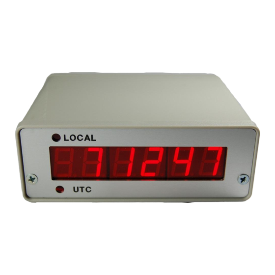
This clock has 6 digits for hours, minutes and seconds and the hours display can alternate between two time zones, i.e. Coordinated Universal Time (UTC) and local time. The CLK100 is offered in kit form or fully assembled and tested. The kit is easy to assemble with no surface mount parts. -
Page 6: Parts And Unpacking
GEKCO DIGITAL CLOCK P/N CLK100 ASSEMBLY & OPERATION MANUAL Parts and Unpacking The kit is packaged in the order that the assembly is recommended. Each assembly block has an associated parts bag. Only open a parts bag when called for during assembly to avoid misplacing parts. -
Page 7: Display Board Parts List
DIGITAL CLOCK MODEL CLK100 3.2. Display Board Parts List Clock 100 Display Board Printed Circuit Assembly (PCA) parts kit, P/N DBR100-KIT ITEM REFDES PART NO. DESCRIPTION DS1,DS2,DS3 412-499 LED Display Module 7-Segment 2-Digit 0.56" 434-3110 Socket IC Dip24-300 442-3090 IC LED Display Driver MAX7219CNG... -
Page 8: Main Board Parts List
GEKCO DIGITAL CLOCK P/N CLK100 ASSEMBLY & OPERATION MANUAL 3.3. Main Board Parts List Clock 100 Main Board PCA parts kit, CLK100M-KIT ITEM REFDES PART NO. DESCRIPTION VALUE C3,C4,C5 20-104 Cap mono Cer 50v radial lead 0.1UF C1,C2 21-220 Cap mono Cer COG radial... -
Page 9: Final Assembly Parts List
DIGITAL CLOCK MODEL CLK100 3.4. Final Assembly Parts List Clock 100 Final Assembly Hardware parts kit, P/N CLK100HDW-KIT ITEM PART NO. DESCRIPTION 258-616 Hardware Angle Bracket 4-40 250-1418 Hardware Screw Panhead 4-40 x 1/4” 250-1533 Hardware Screw Panhead 4-40 x 1/8”... -
Page 10: Assembly Notes
GEKCO DIGITAL CLOCK P/N CLK100 ASSEMBLY & OPERATION MANUAL Assembly Notes goggles and hold the leads so they 4.1. TOOLS cannot fly toward your eyes. You will need these tools to assemble your kit. 4.3. SOLDERING Diagonal Cutters • Needle Nose Pliers Soldering is one of the most important •... -
Page 11: Step-By-Step Assembly
DIGITAL CLOCK MODEL CLK100 Step-By-Step Assembly 5.1. Display Circuit Board Figure 1: Display Board Top Side Completed Assembly Figure 2: Display Board Bottom Side Completed Assembly GEKCO INC. Rev 1.1... -
Page 12: Figure 3 Display Board Bottom Side
GEKCO DIGITAL CLOCK P/N CLK100 ASSEMBLY & OPERATION MANUAL Open the Display Board Printed Circuit Assembly (PCA) parts kit, P/N DBR656-KIT Refer to Figure 3 for the following steps. Position the Display Circuit Board with the bottom side facing up as shown... -
Page 13: Figure 4: Display Board Top Side Assembly Pictorial
DIGITAL CLOCK MODEL CLK100 Position the Display Circuit Board with the component side facing up as shown below Figure 4: Display Board Top Side Assembly Pictorial Install the decoupling capacitor. C1: 0.1 uF (104) radial-lead ceramic capacitor R1: 10 kΩ (brn-blk-org-silver) resistor NOTE: Before you install an electrolytic capacitor, look at it and identify the leads. - Page 14 GEKCO DIGITAL CLOCK P/N CLK100 ASSEMBLY & OPERATION MANUAL sure the display is mounted flush with the board and oriented correctly and then solder the rest of the pins. DS1: 7 segment LED display module DS2: 7 segment LED display module...
-
Page 15: Main Circuit Board
DIGITAL CLOCK MODEL CLK100 5.2. Main Circuit Board Figure 7: Main Board Top View 2 C1: 22 pF (22) radial-lead ceramic capacitor Figure 5: Main Board Completed Assembly C2: 22 pF (22) radial-lead ceramic capacitor C6: 10 uF radial-lead electrolytic... -
Page 16: Figure 9: Main Board Top View 4
GEKCO DIGITAL CLOCK P/N CLK100 ASSEMBLY & OPERATION MANUAL circuit board. The circuit will not work properly if The next step is to install the mating connector a diode is installed backwards. between the display board (J1) and the main board (J4). -
Page 17: Initial Tests
DIGITAL CLOCK MODEL CLK100 Locate the RTC module and install on Some of the IC’s you will install in the following clock main board shown. steps are MOS {metal oxide semiconductor) devices. Be sure they do not get damaged by static electricity. -
Page 18: Final Tests
GEKCO DIGITAL CLOCK P/N CLK100 ASSEMBLY & OPERATION MANUAL ) Locate the miscellaneous hardware bag In Case Of Difficulty and attach the angle bracket to the display board using the 4-40 screws and nuts as shown. The “Visual Checks” that are provided below... -
Page 19: Figure 14: Enclosure Cover To Base Assembly
DIGITAL CLOCK MODEL CLK100 Unpack the enclosure parts kit, which includes the front and back panels with bezels, four 4-40 flat head screws and the base and cover pieces. Slide the cover into the base as shown in figure 14. -
Page 20: Figure 18 Enclosure Back
GEKCO DIGITAL CLOCK P/N CLK100 ASSEMBLY & OPERATION MANUAL Figure 18 Enclosure Back This completes the assembly. Congratulations have successfully completed the assembly of the unit and now you can enjoy using a clock that you have assembled yourself. REV 1.1... -
Page 21: Operational Instructions
DIGITAL CLOCK MODEL CLK100 Operational Instructions Pressing the SET button will start the menu selection process. Each button press of the SET button selects the next menu option. If the + or – button is pressed during the time setting mode, the menu loop ends after the seconds setting. -
Page 22: Setting The Alarm Time
GEKCO DIGITAL CLOCK P/N CLK100 ASSEMBLY & OPERATION MANUAL 10.4. Setting the Alarm Time The alarm time can be set. The is done by pressing the SET button until the “Set AL” display is shown. Then press the + (increment) button to set the alarm hours. Press the + or – button to increment or decrement the alarm hours. -
Page 23: Figure 19: Menu Flow Chart
DIGITAL CLOCK MODEL CLK100 MENU ROUTINE START SET LOCAL INCREMEN T/DECREMENT SET 12 HR DISPLAY SELECT HOURS HOURS TIME 12/24 SET 24 HR DISPLAY SET DISPLAY INCREMEN T/DECREMENT INCREMEN T BRIGHTNESS SELECT MINUTES MINUTES BRIGHTNESS LEVEL 0-15 RETURN INCREMEN T/DECREMENT... -
Page 24: Theory Of Operation
GEKCO DIGITAL CLOCK P/N CLK100 ASSEMBLY & OPERATION MANUAL Theory of Operation 11.1. Block Diagram DISPLAY BOARD UTC/LOCAL HOURS MINUTES SECONDS 1 2 3 0 5 9 DISPLAY DRIVER MAIN BOARD MENU REAL TIME CLOCK MICROCONTROLLER PLU S MINUS (OPTIONAL) -
Page 25: Main Board Circuit Description
This device uses a 3 wire, I2C interface to communicate with the microcontroller. Connector J2 is the programming interface connector. This allows the firmware to be modified and the ability to reprogram the microcontroller. The CLK100 board looks just like a Arduino Uno and can use the popular Arduino IDE. -
Page 26: Firmware
GEKCO DIGITAL CLOCK P/N CLK100 ASSEMBLY & OPERATION MANUAL Firmware 12.1. Flow Chart MAIN LOOP MENU MODE? DISPLAY MENU UPDATE TIME SWITCH PRESS? MENU BUTTON? MENU ROUTINE Figure 21: Software Flowchart 12.2. Firmware Design Description There are two basic modes of operation. -
Page 27: Pca Pictorial Diagrams
DIGITAL CLOCK MODEL CLK100 PCA Pictorial Diagrams 13.1. Main Board Figure 22: Main Board Top Figure 23: Main Board Bottom GEKCO INC. Rev 1.1... -
Page 28: Display Board
GEKCO DIGITAL CLOCK P/N CLK100 ASSEMBLY & OPERATION MANUAL 13.2. Display Board Figure 24 Display Board Top Side REV 1.1 GEKCO INC. -
Page 29: Figure 25 Display Board Bottom Side
DIGITAL CLOCK MODEL CLK100 Figure 25 Display Board Bottom Side GEKCO INC. Rev 1.1... -
Page 30: Schematic Main Board
GEKCO DIGITAL CLOCK P/N CLK100 ASSEMBLY & OPERATION MANUAL Schematic Main Board REV 1.1 GEKCO INC. -
Page 31: Schematic Display Board
DIGITAL CLOCK MODEL CLK100 Schematic Display Board GEKCO INC. Rev 1.1... -
Page 32: Customer Service
GEKCO DIGITAL CLOCK P/N CLK100 ASSEMBLY & OPERATION MANUAL Also include switch positions, connections to CUSTOMER SERVICE other units, operating procedures, voltage readings, and any other information you think might be helpful. Please provide complete information when you request replacement parts from the factory. Be... -
Page 33: Document Revision History
DIGITAL CLOCK MODEL CLK100 Document Revision History 18-Nov-18 Initial Release 21-Jan-5 Updated with Main Board Rev B GEKCO INC. Rev 1.1...
Need help?
Do you have a question about the CLK100 and is the answer not in the manual?
Questions and answers