Table of Contents
Advertisement
Quick Links
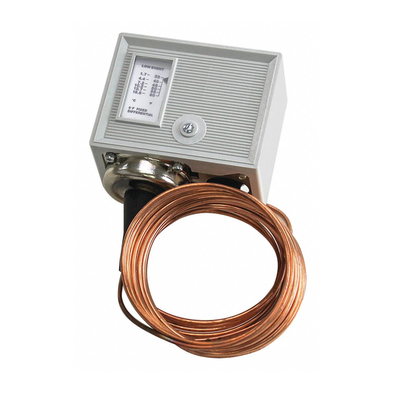
Application
The TC-5231, TC-5232, and TC-5241 low temperature
thermostats are used to control temperature in air
conditioning
or
refrigeration
temperature thermostat measures the coldest one-foot
section along the entire 20-foot sensing element.
The low temperature thermostats are applicable to
various applications such as: low temperature control
of steam coils; frost indication in storehouses or
orchards; temperature control of freezer cabinets,
display cases, beverage coolers, milk cooling tanks,
and air conditioners.
Features
•
20 ft. (6.1 m) element senses temperature over a
large area. Control responds to coldest one-foot
section of the sensor.
•
Adjustable setpoint from 35 to 60°F (1.7 to 15.5°C)
with 5°F (3°C) fixed differential.
•
SPDT and DPST versions.
•
Rated for use at 17 full load amps (120/208/240
Vac), 24 non-inductive amps (120/208/240 Vac),
and 16 non-inductive amps (24 Vac). Capable of
controlling refrigeration equipment directly.
•
UL and CSA approved.
•
Capillary clips provided.
Applicable Literature
•
TAC Electric/Electronic Products Catalog, F-27382
•
Environmental Controls Application Manual,
F-21335
Printed in U.S.A. 8-06
TAC
1354 Clifford Avenue
P. O. Box 2940
Loves Park, IL 61132-2940
www.tac.com
systems.
The
low
© Copyright 2006 TAC All Rights Reserved.
TC-5231 Series, TC-5232,
& TC-5241 Series
Low Temperature Thermostats
General Instructions
F-25911-5
Advertisement
Table of Contents

Related Manuals for t.a.c. TC-5231 Series


Summary of Contents for t.a.c. TC-5231 Series
- Page 1 TC-5231 Series, TC-5232, & TC-5241 Series 1354 Clifford Avenue P. O. Box 2940 Loves Park, IL 61132-2940 www.tac.com Low Temperature Thermostats General Instructions Application The TC-5231, TC-5232, and TC-5241 low temperature thermostats are used to control temperature in air conditioning refrigeration systems.
- Page 2 SPECIFICATIONS Setpoint Dial Range: Dual marked 35 to 60°F (1.7 to 15.5°C). Sensing Element: Vapor pressure type, copper construction. Response: To lowest temperature sensed by any one-foot section of its element. Altitude causes the control to operate approximately 1°F colder per 1000 ft. of elevation. Differential: 5°F (3°C) fixed.
- Page 3 TYPICAL APPLICATIONS (wiring diagrams) Indication AC Supply Motor Circuit Earth Ground Temp Drop 1 Terminals (2) and (1) close on temperature drop. Figure-1 TC-5231 and TC-5241 Typical Application. AC Supply Motor Indication Circuit 2 Terminals L-T open on temperature drop. Note: Contacts are not rated for dry circuit applications.
- Page 4 W A R N I N G • The TC-5231 series, TC-5232, and TC-5241 series devices are designed for use only as operating controls. Where an operating control failure would result in personal injury and/or loss of property, it is the responsibility of the installer to add devices (safety, limit controls) that protect against, or systems (alarm, supervisory systems) that warn, of con- trol failure.
- Page 5 2. Provide a drip loop in the capillary if the body is mounted in any position other than upright. The thermal element is usually located on the downstream side of the coil. 3. Allow slack so that the capillary is not taut. Install the thermal element securely in the controlled media for maximum sensing capability and minimum vibration damage.
- Page 6 Wiring N O T E Do not adjust the pointer beyond the highest and lowest marks on the scaleplate. The scaleplate is only for reference, and the final settings should be verified with a thermometer. C A U T I O N The terminals must not be bent, cut off, drilled, or retapped.
- Page 7 CHECKOUT C A U T I O N The unit includes a mechanical stop to prevent adjustment below 35°F (2°C). Do not attempt to set below 35°F (2°C), or the device may be damaged. 1. If the ambient temperature at the thermal element is within the 35 to 55°F (2 to 13°C) set- point range, turn the adjustment screw located in the top of the case until the setpoint exceeds the ambient temperature.
- Page 8 DIMENSIONAL DATA Dimensions are shown in inches (millimeters). Front View Side View 3-1/2 (89) Max. 2 Max. (51) 2-15/32 (63) 1-3/4 2-45/64 (69) Max. (45) Two Mounting Holes 2-3/16 (56) for #10 Screws 2-1/16 (52) Opening for 1/2" Conduit Fitting this Surface Figure-6 TC-52xx Mounting Dimensions.
Need help?
Do you have a question about the TC-5231 Series and is the answer not in the manual?
Questions and answers