Advertisement
Quick Links
SOLUTIONS
DESCRIPTION
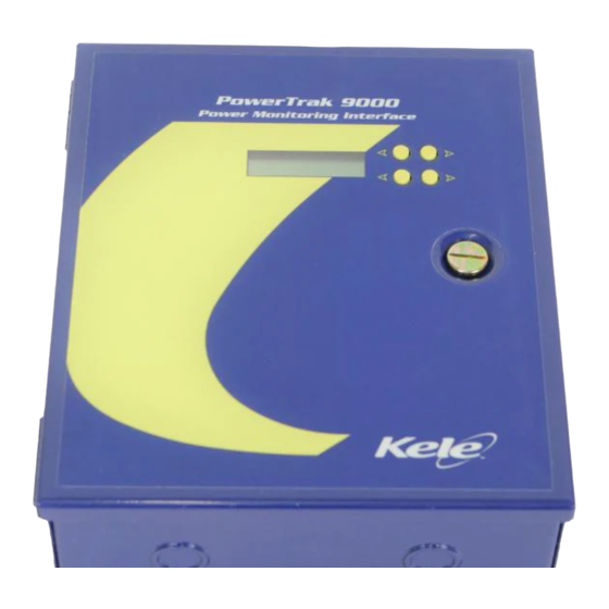
The PowerTrak Series Power Monitoring Interface moni-
tors numerous power system parameters for local display
and/or remote connection to a BAS or other data acquisition
equipment. Any three-phase or single-phase 50/60 Hertz elec-
trical system from 120 to 600 volts can be monitored by the
PowerTrak without the need for potential transformers. Higher
voltage systems such as 5 kVolt or 15 kVolt services can also
be monitored using potential transformers. The PowerTrak is
available for use with 1 amp, 5 amp or 0.333 volt current trans-
formers. Options include a current transformer shorting
assembly and a digital LCD display.
Furnished in a NEMA 1 hinged cover enclosure with external
mounting feet and conduit knockouts on all sides, the
PowerTrak is simple to install. Setup of the PowerTrak is eas-
ily accomplished with a selector switch and DIP switches. A
truly unique feature of the PowerTrak is its ability to identify
and electronically correct wiring problems such as reversed
CT polarities or improper phasing of voltages with CT's.
FEATURES
•
Auto-corrects for wiring errors
•
Three-phase (Wye or Delta) or single-phase systems
•
Voltage selector switch (120-600V)
•
Accepts 5 amp, 1 amp or 0.333 Volt CT's
•
Low voltage alarm contact
•
Two 4-20 mA outputs
•
Pulse output for KWH with selectable pulse rate
•
Optional two line LCD display
•
Optional unique CT shorting assembly
•
Easily installed enclosure with external mounting feet
•
Optional LonWorks communications
SPECIFICATIONS
Inputs:
System type
Three-phase (Wye or Delta),
Single-Phase
Input voltage
120 to 600 VAC
Frequency
50/60 Hz
Input current
0-5 amp or 0-1 amp or 0-0.333 volts
CT Burden
0.75 VA maximum (1A or 5A inputs)
PT Burden
4.8 VA maximum
Fusing
0.5 A, 600 V (KLK-0.5)
Outputs:
Pulse output
Pulsed contact closure for KWH
Solid state relay, 50 VAC/DC max,
100 mA max
Pulse rate
Four selectable KWH per pulse
rates, 50% duty cycle
Maximum pulse rate
Five pulses per second
Contact output
Maintained contact closure for
low voltage alarm
50 VAC/DC, 100 mA max
KELE • www.kele.com • FAX 901-372-2531
POWERTRAK POWER MONITORING INTERFACE
APPLICATION
PowerTrak Applications:
Remote (Outputs) & Local (Display) Monitoring
KWH
Window KW
Total KVA
True RMS Voltage
Local (Display) Monitoring - Each Phase
True RMS Voltage
True RMS Current
KW (Wye systems)
KVA (Wye systems)
Power Factor (Wye systems)
Analog outputs
Analog output max load 725 ohms each output @ 24 VDC
Analog output power
Accuracy
Operating temperature
Humidity
Display option
Dimensions
Weight
Approvals
* Voltage and current outputs are the average of the three-
phase true RMS values.
PT-9000 SERIES
A Kele Company
C
R
R
SHOWN WITH OPTIONAL DISPLAY
Total KW
Peak Window KW
Total Power Factor (PF)
True RMS Current
Two (2) externally powered
4-20 mA signals selectable
for total KW, window KW,
peak window KW, total power factor,
total KVA, RMS current*, or
RMS voltage*
External 24 VDC @ 60 mA max
0.75% of F.S. (KW, KVA, VOLTS, AMPS)
± 0.03 PF (40 to 100% F.S. power)
32° to 122°F (0 to 50°C)
5-95% noncondensing
LCD, Two lines, 16 characters/line
12"H x 10"W x 4"D
(30.5 cm x 25.4 cm x 10.2 cm)
12 lbs (5.5 kg)
UL and CUL listed, file #E161500
USA 901-937-4900 • International 901-382-6084
July 1999
TM
rev. 5/98
Advertisement

Related Manuals for Kele PowerTrak Series


Summary of Contents for Kele PowerTrak Series
- Page 1 PT-9000 SERIES SOLUTIONS DESCRIPTION A Kele Company The PowerTrak Series Power Monitoring Interface moni- tors numerous power system parameters for local display and/or remote connection to a BAS or other data acquisition equipment. Any three-phase or single-phase 50/60 Hertz elec- trical system from 120 to 600 volts can be monitored by the PowerTrak without the need for potential transformers.
-
Page 2: Installation
PowerTrak and the current transformers as well as to the gauge of the CT wiring. Refer to the Technical Reference section in the Kele catalog for more information on burden or call Kele. - Page 3 The peak window KW value can be reset to zero by pressing the CLEAR PEAK KW button inside of the PowerTrak or by momentarily interrupting power to the current loop connected to MA OUT 2 terminals. KELE • www.kele.com • FAX 901-372-2531 USA 901-937-4900 • International 901-382-6084...
- Page 4 KW on the display or the highest mA reading on the meter. Manually set the PowerTrak to the cor- rect configuration using the CT POL & VA MATCH push buttons. KELE • www.kele.com • FAX 901-372-2531 USA 901-937-4900 • International 901-382-6084...
- Page 5 NOTE: For Wye and single phase systems, low voltage is measured line-to-neutral. For Delta TABLE 2 LOW VOLTS ALARM THRESHOLD systems, low voltage is measured line-to-line. Low Volts Threshold Switch A3 Switch A4 Switch A5 Switch A6 Switch A7 Switch A8 KELE • www.kele.com • FAX 901-372-2531 USA 901-937-4900 • International 901-382-6084...
- Page 6 TABLE 5 CT RATIO SELECTIONS (5 Amp or 1 Amp or 0.333 Volt CT’s) CT Primary Switch C1 Switch C2 Switch C3 Switch C4 Switch C5 1000 1200 1500 1600 2000 2500 3000 3500 4000 5000 6000 KELE • www.kele.com • FAX 901-372-2531 USA 901-937-4900 • International 901-382-6084...
- Page 7 (FOR SYSTEMS GREATER THAN 600V) Fuse per N.E.C. for conductor size & type. POTENTIAL TRANSFORMER Connection option using one open delta 3PT3 3-Phase Potential Transformer with 120 VAC secondary. KELE • www.kele.com • FAX 901-372-2531 USA 901-937-4900 • International 901-382-6084...
-
Page 8: Analog (4-20 Ma) Outputs
PowerTrak. The peak window KW value is updated on thirty second intervals and will change in value only if the current sliding window KW value is greater than the current peak window KW value. KELE • www.kele.com • FAX 901-372-2531 USA 901-937-4900 • International 901-382-6084... - Page 9 The Total Power Factor parameter is a measure of the power factor (0 to 1) for a three-phase electrical system. PF = 1 x (mA out - 4) Where, PF = Total Power Factor mA out = PowerTrak milliamp output value KELE • www.kele.com • FAX 901-372-2531 USA 901-937-4900 • International 901-382-6084...
-
Page 10: Digital Outputs
N = total number of pulses accumulated at the controller input KWH per pulse = KWH per pulse setting at DIP switches B1-B2 (See Table 3). PT Ratio=PT Primary/PT Secondary. Example: 4800V to 120V PT Ratio=4800/120=40 KELE • www.kele.com • FAX 901-372-2531 USA 901-937-4900 • International 901-382-6084... - Page 11 The LED is “OFF” when any phase voltage drops below the low voltage alarm setting. Contact Open = All phase voltages above low-voltage alarm setting. Contact Closed = All phase voltages below the low-voltage alarm setting. AREA FOR CALCULATION AND NOTES KELE • www.kele.com • FAX 901-372-2531 USA 901-937-4900 • International 901-382-6084...
-
Page 12: Ordering Information
___13. If equipped with the display option, verify that all parameters display a value. ___14. Verify that all output signals used are working properly. If you have any questions, call Kele at 901-937-4900, FAX 901-372-2531 or e-mail info@kele.com. ORDERING INFORMATION...
Need help?
Do you have a question about the PowerTrak Series and is the answer not in the manual?
Questions and answers