Table of Contents
Advertisement
Advertisement
Table of Contents

Summary of Contents for Etrel load guard
- Page 1 ETREL LOAD GUARD USER MANUAL Document version: 2.1 Document date: 30. 7. 2020...
-
Page 2: Table Of Contents
Pairing of Load Guard to Charging Station ........18 Pairing of Charging Station with Load Guard ....... 19 TROUBLESHOOTING ..............22 Configuration Software Can Not Find the Load Guard ....22 No Connection Between Load Guard and Charging Station .... 22 Serial Number is Not Valid ............... 23 Load Guard Does Not Measure Voltage .......... -
Page 3: Preface
Etrel Load Guard | User manual PREFACE Load guard is a sensor that is installed in the building’s electric cabinet. It measures the electric current in the building’s installation and sends real- time measurements to the charging station. INCH charging station responds to received data by reducing the charging... -
Page 4: Where To Use Load Guard
PREREQUISITES FOR USE • Load Guard connected to the mains and LAN. • A computer connected to the same LAN as the Load Guard. • Load guard configuration program (Load Guard Configurator). • INCH charging station (set up as a master) connected to the same... -
Page 5: Load Guard
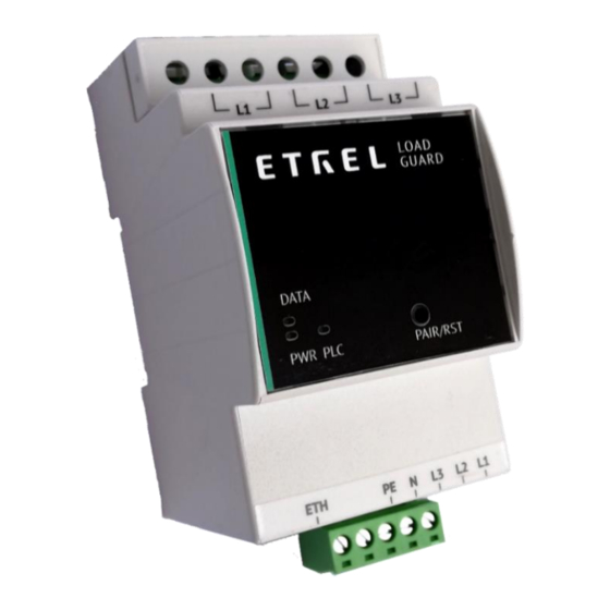
Figure 3: LED lights of Load Guard The Load Guard has three LEDs on the front plate labelled PWR, DATA and PLC. When the Load Guard is connected to the power supply, the PWR light should light up. If the connection between the Load Guard and the charging station is established, the DATA light flashes. -
Page 6: Technical Specifications
16 mm in diameter) and 400 A current clamps (for conductors up to 24 mm in diameter). The length of the wires for connecting the current clamps to the Load Guard is 70 cm. Figure 5: Load Guard with connected measuring current transformers TECHNICAL SPECIFICATIONS DIMENSIONS 90.5 x 53.5 x 61.8 [mm]... -
Page 7: Connecting The Load Guard
Etrel Load Guard | User manual CONNECTING THE LOAD GUARD Load Guard is installed in electrical cabinet, after the main counter. It measures currents of all phases and is sending the measurements to the charging station in real time to ensure that the overload of the fuses cannot happen. -
Page 8: Load Guard Current Transformers
Etrel Load Guard | User manual LOAD GUARD CURRENT TRANSFORMERS Figure 7: Dimensions of current transformers CONNECTING THE CURRENT TRANSFORMERS Figure 8: Connecting the current transformers THREE-PHASE CONNECTION For proper three-phase connection, current clamps must be placed on specific phase conductors. - Page 9 The following figure shows the current clamp cables connection for all three phases (L1, L2 in L3) from left to right. The phase conductors for powering the Load Guard must be connected in the same way (from right to left). Positions for...
-
Page 10: Single-Phase Connection
(from clamps to the consumers). If the direction of measuring current transformer is wrong, Load Guard will be measuring negative power. If this happens, turn the measuring current transformer correctly. -
Page 11: Production Of Energy At The Location
(photovoltaic cells, batteries, ...), the measuring current transformers can be set on two conductors (production conductor and consumption conductor). In this case the Load Guard would be measuring the difference of consumption and production currents and would enable higher charging current in time of production. -
Page 12: Obtaining Ip Adress Of Computer And Charging Station
CHARGING STATION To enable configuration of the Load Guard and of the charging station, the computer, Load Guard and charging station need to be in the same network segment: 192.168.1.xxx. First three numbers must be the same and the fourth must be different among the devices. -
Page 13: Charging Station Ip Address
The part of the IP address that is inside of red rectangle must be the same as it is written in the Load Guard Configuration Software settings. If this is not true, the software could not find the Load Guard and even if Load Guard is found, the configuration is not possible. - Page 14 Etrel Load Guard | User manual Figure 20: Display of IP address after pressing the reset button for 5 s Figure 21: Selection of login mode The IP address of the charging station and the state of the connection with central system will be displayed.
-
Page 15: Configuration
/258867203/Load Guard Configurator 1.4.zip?api=v2 Expand the compressed file in new folder Load Guard Configurator 1.4. Click on LoadGuardConfigurator.exe inside the folder opens software for configuration of Load Guard. The message of Windows Firewall will be presented. - Page 16 Enable the access as shown on the previous figure. Then click on the Allow access and enable the configuration of the Load Guard. If the software finds the Load Guard in its network, the data of Load Guard will be presented on the screen.
-
Page 17: Configuration Of The Load Guard
Serial number of the charging station that is used to connect Load Guard to. LOAD GUARD NETWORK SETTINGS Click on the white part of the screen (the line with Load Guard data) opens the configuration window. Figure 27: Windows for configuration settings Default IP address of the Load Guard is 192.168.1.249. - Page 18 Figure 29: Load Guard is not in the same network group as computer If the IP address of the Load Guard was changed in a way that the Load Guard is not part of the same network group as the computer anymore (e.g.
-
Page 19: Charging Station Serial Number
Serial number of charging station can be found in charging station web interface. After the login to the web interface Diagnostics must be selected in Etrel menu. The serial number of the charging station will be displayed as shown on the below figure:... -
Page 20: Pairing Of Charging Station With Load Guard
The time interval can be set between values 500 ms and 5000 ms (default setting is 750 ms). In the Measurements window it is selected which data will be Load Guard sending to the charging station. To send all the data, the option All must be selected. - Page 21 Figure 35: Connection with Load Guard is established Serial number of the Load Guard must be written in the field Serial number (in the presented case this number is 18430011). After that click on Save and restart the charging station.
- Page 22 • Power [kW] and current [A] of phase L3. If the connection with the Load Guard is not successful, or the connection is interrupted, red dot will show at the Load Guard icon. The Load Guard Configuration software windows should look as it is presented on the following figure.
-
Page 23: Troubleshooting
(Ctrl+F5). If this does not resolve the issue, perform reset of the charging station and reset the Load Guard as well. Sometimes click on the Sync device time helps. If the time on the Load Guard is not synchronized, the connection will not work correctly! Try connecting to other charging station with the selection of option Charger redundancy supported. -
Page 24: Serial Number Is Not Valid
LOAD GUARD DOES NOT MEASURE VOLTAGE When Load Guard is connected only in single-phase connection and in the “Load Guard Configurator” windows, the voltage is not shown, or it is very low (~5 V) it means that the supply of phase and neutral conductors of Load Guard are switched. -
Page 25: Negative Value Of Active Power
Etrel Load Guard | User manual NEGATIVE VALUE OF ACTIVE POWER If the Load Guard Configuration windows is showing negative active power this could mean the following: • Measuring current transformer is not turned correctly on the phase that is showing negative active power, or the conductors...
Need help?
Do you have a question about the load guard and is the answer not in the manual?
Questions and answers