Table of Contents
Advertisement
Quick Links
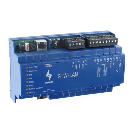
Front view
LAN gateway for remote data transfer
Features
Data interface to the systems with Wurm control
Identification of 4 Frigolink master modules
Real-time clock and synchronisation of the day/night function for the entire system
Fault forwarding of alarms to 2 different destinations
Handling of 2 FIO001B or FIO-PAT input/output modules for additional fault/operation inputs
and relays for provision of 4 alarm priorities
Two relays for central alarm of the overall system (Prio 1 and Prio 2) or for alternative functions
priority-free central alarm and router reset
Data memory for signal history
8 LEDs for status display
Temporary suppression of the fault report for work on the system using the Service key
Direct connection of a CAN USB to the service socket
Connection to the Wurm system via a communication bus (CAN bus) and Frigodata XP
GTW-LAN_PI_2015-02_EN
Subject to technical changes
GTW-LAN
Product information
Page 1 of 4
Advertisement
Table of Contents

Related Manuals for WURM GTW-LAN


Summary of Contents for WURM GTW-LAN
- Page 1 Temporary suppression of the fault report for work on the system using the Service key Direct connection of a CAN USB to the service socket Connection to the Wurm system via a communication bus (CAN bus) and Frigodata XP GTW-LAN_PI_2015-02_EN Subject to technical changes Page 1 of 4...
- Page 2 Wurm GmbH & Co. KG Elektronische Systeme. Keep these instructions ready to hand for quick reference and pass them on with the device when the product is sold.
- Page 3 GTW-LAN Product information Circuit diagram Mount WARNING! Danger of death from electric shock! Switch power off to the entire system when installing! Otherwise, external voltage can be present even when control voltage is shut off. The device has been designed for profile rail mounting. The housing is a standard size and is also suitable for installation in fuse boxes.
- Page 4 GTW-LAN Product information Functional earth connection Note! We expressly point out that the functional earth connection must be connected with the accompanying cable and the earth terminal. The earth terminal must be placed on the top-hat rail. Earthing is required to ensure trouble-free function.
Need help?
Do you have a question about the GTW-LAN and is the answer not in the manual?
Questions and answers