Advertisement
Quick Links
Specifi cations
Power Supply
Model
Power Voltage
Option
24U
21-27VAC/DC
120
100-125 VAC 50-60Hz
240
200-250VAC 50-60Hz
Input
RC Type Rogowski Coils
Line voltage to 600VAC max.
Output
Modbus RTU (RS485)
KWH pulse contact, 40mA
50VDC max.
Accuracy
< 1% (10-100% of range)
Linearity
< 0.5%
Isolation Voltage
2500 VAC
Frequency Range
50-60 hertz auto select
Operating Temp.
14 - 122 Deg. F
(-10 to +50 deg C)
Enclosure
UL94 V0 Rated
Environmental
0–95% RH
EMC/Immunity
EN50081-1, EN50082-2
Listings
Designed to Meet UL/CUL &CE
Coils
RC1 - 0-500 A, 3.25" ID 3 meter
long leads
RC2 - 0-2000 A, 5.25" ID 3 meter
long leads
Dimensions
4.37 in.
111mm
2.6 in.
65.91mm
3.38 in.
85.83mm
Model Number Key
APN - 600 - RC1 - 120 - MOD
Usage
180mA
50mA
25mA
VOLTAGE INPUT RANGE:
600 - Line voltage 0 - 600 VAC
POWER MONITOR TYPE:
APN - AC Power Monitor, Digital Output
Know Your Power
Other NK Technologies Products Include:
AC & DC Current Transducers
AC & DC Current Operated Switches
1φ & 3φ Power Transducers
Current & Potential Transformers (CTs & PTs)
7.43 in.
188.66mm
Buy: www.ValinOnline.com | Phone 844-385-3099 | Email: CustomerService@valin.com
OUTPUT TYPE:
MOD - Modbus RTU (RS485)
POWER SUPPLY:
24U - 24VAC/DC
120 - 120VAC
240 - 240VAC
CURRENT INPUT:
RC1- Rogowski Coils 0-500 A
RC2- Rogowski Coils 0-2000 A
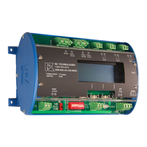
INSTRUCTIONS
APN SERIES
AC Power Monitor
RC Type Current Sensors
Modbus RTU Output
Quick "How To" Guide
1. Current sensing coils are matched with monitor
2. Mount the monitor to a DIN rail using integrated
mounting clips on backside of power monitor.
3. Connect non-energized 3 phase input voltage (term.
2-4, neutral 1 if used) . 1 amp fuses are recom-
mended.
4.
Connect Current Coil (RC) Inputs (term. 5-10).
The white wire from a coil is positive or phase in-
dicator (6-8-10). Be certain the RC coil label faces
the source power.
5. Select baud rate, network address
6. Connect network output (term. 11-13)
7. Connect power supply (term. 16-17)
8. Connect kWH pulse output if needed
9. Energize the monitor and primary circuit.
APN -RCInstruction Sheet Rev 4 5/15 P/N791000007
(term. 14-15)
Advertisement

Related Manuals for NK TECHNOLOGIES APN Series

Summary of Contents for NK TECHNOLOGIES APN Series
- Page 1 Dimensions Connect Current Coil (RC) Inputs (term. 5-10). The white wire from a coil is positive or phase in- Other NK Technologies Products Include: dicator (6-8-10). Be certain the RC coil label faces AC & DC Current Transducers 4.37 in.
- Page 2 Description Modbus Address and Baud Rate Set Up Screens APN Series Power Monitors are designed to monitor AC The node address is set When the fi eld input connections have been made (Rogowski coils and line voltage), and the monitor is powered up, the LCD will display the...
- Page 3 About MODBUS and the APN Power Monitor Press any button to show your display options again. Press Pulse Contact Connection MODBUS® Protocol is a messaging structure, widely the button below “PwrFtr” to display the power factor of Use an external resistor of used to establish master-slave communication between each phase.
- Page 4 Table 1 Register Map - Read Only About MODBUS and the Monitor (continued) Register Address Type Description 8 data bits, with the least signifi cant bit sent fi rst the fi rst fi eld (the address fi eld) is 40001 Integer, 16 bit Volts RMS Phase A, MSB * 10 received, the Monitor decodes...