Advertisement
Quick Links
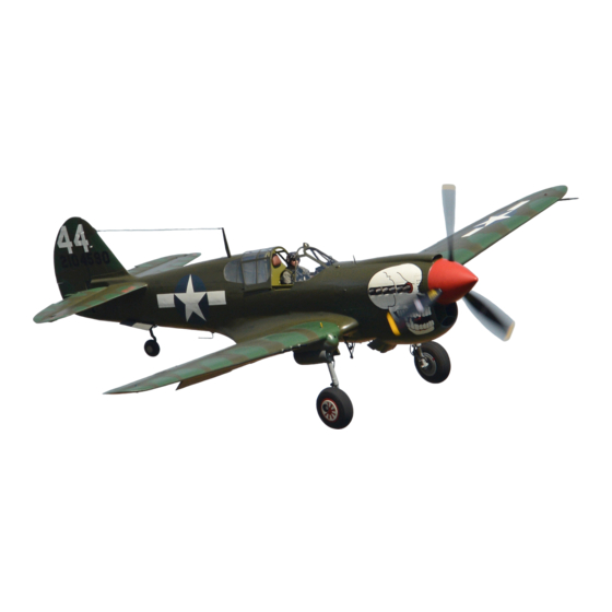
P-40 Tomahawk manual
This manual probably accompanied the AVG Tomahawks to Rangoon. It was
published by the British Air Ministry, and the title page says "Tomahawk
I". However, internal evidence (the engine designation and references to
the Royal Air Force blocks from which the China-bound Tomahawks were
taken) tie it to the Tomahawk IIBs sent to Burma for the AVG. On the other
hand, there is also some internal evidence (i.e., references to French
instrumentation) that the text was not brought entirely up to date, and
that some paragraphs may apply to the Tomahawk I or IIA models.
I copied the manual in 1989 at the National Air & Space Museum, which in
turn had copied it and other material from Larry Pistole's large
collection of AVG memorabilia. Pistole's collection was later acquired by
the Flying Tigers Association, and NASM's copies somehow went missing, so
this is the only version known to be accessible.
I follow the original as exactly as possible, including spelling and
typography. Words in brackets [like this] have been added. Comments
beginning DF: are by the webmaster; those beginning ES: are by Erik
Shilling, a pilot with the AVG, who read the manual with an eye to
comparing it with his memory of the AVG Tomahawks. Erik's comments (with
other information) seem to suggest that the planes sent to China may have
had components of older aircraft installed, possibly so Curtiss could use
up its inventory of parts, and that the planes were actually closer to IIA
models than the IIBs shown in Curtiss records. --
FOR OFFICIAL USE ONLY
AIR PUBLICATION 2013A
Pilot's Notes
PILOT'S NOTES
TOMAHAWK I
ALLISON V-1710-C15 ENGINE
INTRODUCTION
1. The Tomahawk I is a single-seater, low wing, monoplane with retractable
landing gear and enclosed cockpit, powered with an Allison V-1710-C15
engine, which drives a Curtiss multi-position, constant speed,
electrically operated, tractor propeller. The following are the main
dimensions:
Span 37 ft., 3 1/2 in., Overall length 31 ft. 8-9/16 in.
Overall height with tail down 9 ft., 7 in.
2. The cockpit is totally enclosed. The windscreen is in three sections of
laminated glass and behind the windscreen there is a section of 1-1/2 inch
glass for protection from gunfire. The transparent cabin cover slides fore
and after for entry and exit purposes. An emergency release is provided by
which the entire sliding section has an emergency exit on the port side,
for us in event of turnover. The structure behind the pilot is of
sufficient strength to withstand a turnover landing. Three pieces of armor
plate are provided; one piece 7 mm. thick ahead of the pilot from the
windscreen line down to the top of the engine, a piece 7 mm. thick behind
the pilot's back, and 9 mm. thick behind his head.
3. The main plane is a cantilever multi-spar, skin stressed type built in
two pieces and joined at the centerline of the airplane. The wing tips are
detachable. The joint where the two wing sections are connected will serve
as a skid in case of an emergency landing with the wheels retracted.
The ailerons are both dynamically and aerodynamically balanced. They are
operated by the conventional stick control. A fix type trimming tab,
adjustable in the ground is provided on
4x 4
Šeach aileron. The
Advertisement

Summary of Contents for Curtiss P-40 Tomahawk
- Page 1 AVG Tomahawks. Erik's comments (with other information) seem to suggest that the planes sent to China may have had components of older aircraft installed, possibly so Curtiss could use up its inventory of parts, and that the planes were actually closer to IIA models than the IIBs shown in Curtiss records.
- Page 2 ailerons have a stressed metal skin leading edge and are fabric covered. The flaps are of the split trailing edge type, extending from the aileron to near the centerline of the airplane and are operated hydraulically by an electrically driven pump or by an emergency hand pump. An indicator on the instrument boards shows the position of the flaps at all times when the battery switch is on.
- Page 3 17. First Aid Kit - is located on the port side of fuselage being accessible through fuselage service door. 18. Propeller - The propeller is a Curtiss multi-position and/or constant speed type. The propeller is operated electrically from the airplane...
- Page 4 Pilot's manual for the Curtiss Tomahawk (cont'd) Stuff in brackets [like this] has been added. Those beginning ES are by Erik Shilling, a pilot with the AVG 3rd Squadron. SECTION 1 Pilot's Controls and Equipment Introduction This section gives the location and, where necessary, explains the function of the controls and equipment in the pilot's cockpit.
- Page 5 is located below the instrument board and may be engaged by being pulled back when the pedals are depressed. It is automatically disengaged when the pedals are depressed. 6. Trim Tabs - The adjustable trim tabs for the rudder and elevators [sic] controls are located at the port side of the cockpit near the pilot's seat, and work in the same plane as the controls concerned.
- Page 6 tail wheel which was left retracted.] Before starting engine or taxiing, check landing gear lock by shifting selector to "down" position and operating the hand pump until it is solid to fore and aft movement. Return valve lever to neutral position. 8.
- Page 7 event, the pitch should be changed only if absolutely necessary.) The desired R.P.M. can then be obtained by moving the constant speed control lever on the throttle quadrant. Manual Control - Set switch from "on" (automatic control) to "Hand Control". The throttle quadrant lever is then cut out and any change in R.P.M.
- Page 8 that the manual is in error, or that the planes diverted to China were not equipped the same as those sent to North Africa for the RAF.] In case of battery failure, the started may be cranked by hand with crank and extension provided for this purpose, both being located in rear access compartment.
- Page 9 cockpit. (Aircraft Nos. A.H. 741 to A.H. 990 have one bottle only) [ES: We did not have the oxygen as shown since it was a high pressure system, not the low pressure demand system.] 23. Aircraft Flares - Two M-8 type flares are carried in the flush type built-in wing flare racks.
- Page 10 SECTION 2 HANDLING AND FLYING NOTES FOR PILOT INTRODUCTORY NOTES Note: - These notes should be read in conjunction with the Flying Training Manual, Part 1, Chapter III, which sets forth in detail the technique which is only outlined here. 1.
- Page 11 accordance with the weight sheet summary and ascertain that the aeroplane is in all other respects fit for flight. PRELIMINARIES 3. Before starting the engine, check the following: (i) That the ignition switches are OFF; (ii) That undercarriage, tail wheel, and flap selectors are in NEUTRAL; (iii) That constant speed toggle switch on control panel is ON;...
- Page 12 26 in. Hg. (65 Cm.Hg.) Note:- Care must be taken to see that the tail does not lift when 1800 r.p.m. is exceeded, and it is advisable to have somebody holding this down whilst running up. (viii) Reset propeller switch to "automatic" position and check C.P. controls.
- Page 13 column. When the flaps are up return the lever to neutral. (vi) Set mixture control to automatic rich. ENGINE FAILURE DURING TAKE-OFF 10. If the engine should fail during take-off, put the nose of the machine down and maintain flying speed. See that the undercarriage has commenced to come up and, if possible, select the "DOWN"...
- Page 14 aircraft, and loads of over 5g. can be applied to 180 to 200 m.p.h. without the aircraft stalling. The stalling speeds of the aircraft at normal operational loads, were as follows: Undercarriage up and flaps up - 80 I.A.S. Undercarriage down, flaps up - 82 I.A.S. Undercarriage up, flaps down - 73 I.A.S.
- Page 15 out on this aircraft. Due to the controls being powerful and moderately light the aerobatic qualities are good, but great care must be exercised to see that all aerobatics are carried out at sufficient height to enable the pilot to recover from a dive without exerting excessive loads on the aircraft.
-
Page 16: Forced Landing
(i) For the engine off approach, a speed of 95 to 100 m.p.h. should be maintained. This will give a steep angle of glide and a good view will be obtained of the landing area. Control at these speeds is good. (ii) An engine assisted approach should be carried out at approximately 90 to 95 m.p.h. - Page 17 NOTES ON THE ALLISON V-1710-C15 ENGINE (Using 100 Octane Fuel) 27. The following should be carefully noted: (i) Limited operational conditions Take-off * Maximum r.p.m. 3000 Maximum boost at S.L. 41.0 in.Hg. Maximum boost above 2600 ft. 38.9 in.Hg. Mixture control below 3500 ft. "Full-rich" Mixture control above 3500 ft.
- Page 18 Reserve tank 33 gallons [41.25 U.S.] Total 130 gallons [162.5 U.S.] (ii) Fuel consumptions (in Imperial gallons per hour): Approximate consumptions at 12,000 feet are as follows: Climbing ----- at 2600 r.p.m. and 35 in.Hg. boost 84 [105 U.S.] Cruising ----- at 2600 r.p.m. and 35 in.Hg. boost 84 [105 U.S.] -- (mixture at 2280 r.p.m.
- Page 19 carburetor manual mixture control to Automatic-Rich position. Should engine stop, return the manual mixture control to IDLE-CUT-OFF position to avoid flooding the engine with fuel, as the fuel pressure will build up to normal operating pressure (12-14 lbs./sq in.) when engine starts firing.
- Page 20 (b) Overpriming is first indicated by very weak combustion, followed by black smoke discharge from the exhaust. Excessive priming is evidence by wet spark plugs and fuel appearing at the exhaust stacks. (c) As the prime fuel is injected directly into the intake manifolds of each cylinder, excess fuel will not be carried off by the supercharge scroll drain which relieves the scroll housing of excess fuel delivered only by the discharge nozzle which has opened, either by too high fuel...
Need help?
Do you have a question about the P-40 Tomahawk and is the answer not in the manual?
Questions and answers