
Related Manuals for Doran Scales 2200 Series

Summary of Contents for Doran Scales 2200 Series
- Page 1 2200 Series Process Control Digital Weight Indicator Technical Manual MAN346 – Rev 5.3 Doran Scales, Inc. www.doranscales.com...
-
Page 2: Table Of Contents
Table of Contents Introduction ........................... 1 Unpacking Your Scale ........................1 Specifications ......................... 2 Scale Controls and Operation ....................3 Scale Annunciators .......................... 3 Powering On ............................ 4 Basic Weighing Operation ........................ 4 ZERO ..............................4 TARE ..............................5 Keyboard TARE entry ........................5 Display TARE value .......................... - Page 3 Setting Time and Date ........................16 Accumulator and Counter ..................... 17 Accumulator and Counter Operation ..................... 17 Display Accumulator and Counter Values ..................17 Clear Accumulator and Counter ..................... 17 Accumulator and Counter Data String Output to Printer or Data Collection ........17 Installation Guide .........................
- Page 4 External Relay Box Option ....................60 External Relay Setup: ........................61 4-20mA Analog Output Option ..................... 62 Wired Ethernet Option ......................63 Wireless 802.11b/g Ethernet Option ..................64 Troubleshooting Wifi ........................65 Bluetooth Option ........................66 Bluetooth Pairing Instructions ......................67 Troubleshooting ........................
-
Page 5: Introduction
Introduction Thank you for purchasing a Doran Scales product. Please read this manual to ensure obtaining all the benefits that the 2200 can provide. This manual is intended for revision 5.3 and greater scales. If required, Doran can upgrade the software in your scale to the current revision. -
Page 6: Specifications
Specifications NTEP Certificate Class III – 10,000d; Cert. #06-101 CWM Certificate Class III – 10,000d; Cert. #AM-5617 Enclosure 304 Stainless Steel Product Dimensions 10” W x 6.75” H x 3.5” D Environmental Protection IP69K Legal for Trade 14 F to 104F (-10 C to +40 C) Temperature Range Resolution Range 200d to 100,000d... -
Page 7: Scale Controls And Operation
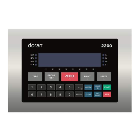
Scale Controls and Operation Fig. 1: Front Panel Scale Annunciators Unit of measure lb, oz, kg, g or lb:oz. The units annunciator to the right of the display will indicate the current unit of measure. Net weighing mode is indicated by the NET annunciator. The annunciator will illuminate when a net weight is displayed. -
Page 8: Powering On
Motion indicator. This symbol represents motion or instability of the weight. The annunciator will illuminate when motion is sensed on the platform. Changes in weight, vibration or air currents can cause the scale to go into motion. 1 to 8 setpoint output status indicators. Below the weight display are annunciators that are illuminated when an output is active in weighing mode or the current setpoint or preact is being edited. -
Page 9: Tare
TARE Place the item you wish to tare on the scale platform and press TARE. The scale will display a net weight and the NET annunciator will illuminate. Tare weights will remain in memory even if the indicator is turned off. Keyboard TARE entry Enter a weight and press TARE to save or press CLEAR to cancel tare entry. - Page 10 Password Protected Values To activate password protection, the PASS parameter must be configured with a numeric password. Once configured, password protection will be activated upon power up. If password protection is activated, the display will show PASS when Setpoint, Preact, Tare, values are displayed.
-
Page 11: Setpoint And Output Operation
Setpoint and Output Operation The 2200 is equipped with eight outputs and eight setpoints. The output must be assigned by the Output Configuration ( 9.7 ouT ) parameter to any of the eight setpoints, remote input, batch program control and threshold weight to activate. A setpoint is a target weight that triggers an output. -
Page 12: Enter Setpoint Preact Weight
For Example: 20 pounds of a material is desired and material in transit is observed and estimated at 0.5 lb. Setpoint 1 is set to 20 lb Preact 1 is set to 0.5 lb Adjustment % is left at the default of 50% After running the process, the final weight is observed to be 20.3 lb Preact = 0.5 lb + 0.5 x (20.3 –... -
Page 13: Tank Level Maintenance Mode
Tank Level Maintenance Mode The F1L Setpoint Operation ( 9.4 S.o. ) maintains a level in a tank between two setpoint target weights. This allows the tank to be drained to a desired amount before being refilled to a maximum target weight. Setpoint 1 will be the low level of the tank, and setpoint 2 will be the high level. -
Page 14: Battery Operation
Battery Operation The 2200 can be optionally configured with a self-contained Rechargeable Sealed Lead-Acid battery and charging circuit, both internal. The scale is designed to run continuously for up to 60 hours with a single 350 ohm load cell. To maximize battery life, leave the auto-off timer enabled which will automatically power down the scale after a period of non-use. -
Page 15: Product Id
Product ID 800 product IDs are available. Deploying a large library of IDs with multiple scales can be easy to manage with Doran’s data management programs. Product IDs save information that includes: • Setpoint values • Preact values • Batch program assigned to product ID •... -
Page 16: Delete Product Id From Memory
To enter and save values for all fields associated with the current Product ID, enter values for each field. When changing products, the display will read SaVed to indicate that all fields associated with the new Product ID number are saved and will be recalled when that product is used again. -
Page 17: Batch Program Operation
Batch Program Operation A batch program uses a series of commands to operate a control process. Operating Mode ( 1.12 oP ) must be set to batch operating mode for batch programs to run. Up to 100 programs can be stored at one time. Each program can contain up to 100 commands. -
Page 18: Batch Commands
Batch Commands Command Description START START button press required. Use to pause a batch that requires user interaction. TARE Performs a TARE operation ZERO Performs a ZERO operation PRINT Performs a PRINT operation Places the indicator in NET mode Note: Setpoint Weight Operation ( 9.5 Suu. ) setting controls setpoint target weight and the net weight may not be the setpoint target weight. - Page 19 Wait Until Stable Halts further operations until a stable weight is achieved Wait for Product ID Pauses until a valid product ID is entered Wait for Keypad Operator enters a valid tare value and presses enter Tare Entry Global Repeat Repeats the operations infinitely Global Repeat 01- Repeats operations up to 99 times...
-
Page 20: Time And Date
Time and Date Setting Time and Date Press and hold decimal point / clock button until date is displayed. The current date flashes on the display. To toggle between the current time and date, press the decimal point button. The display reads tinne when the time is displayed. To change the date: 1. -
Page 21: Accumulator And Counter
Accumulator and Counter Accumulator and Counter Operation When a manual or automatic print function is executed, the accumulator has the currently displayed weight added to its current value and the counter is incremented. To confirm an accumulation and counter operation, the left most display digit will momentarily display an o. -
Page 22: Installation Guide
Installation Guide Fig. 2: Motherboard Layout Removing and Replacing the Rear Panel Before you remove the rear panel, remove AC power. Power down the scale if the optional battery power is present. Removing the rear panel requires a 5/16” nut driver. To replace the rear panel and achieve a tight seal, each screw requires a rubber bonded washer and the gasket needs to be in place. -
Page 23: Load Cell Connection
Load Cell Connection Load cell connections are made through terminal block TB1. The power cord connects to terminal block TB5 adjacent to the transformer. Fig. 3: Load Cell and Power (lower left of board) 4 wire load cell 6 wire load cell J1 Jumper J2 Jumper Load Cell Input (TB1) -
Page 24: Power Connection And Fuse
Power Connection and Fuse Power input is located at terminal block TB5, next to the fuse and black transformer. Neutral Ground Line (Hot) Make sure power is off before replacing the fuse. The scale's fuse (F1) is located next to the power terminal (J1). The scale has a filtered power supply to reduce the effects of normal line noise, but it cannot limit severe fluctuations. - Page 25 TB3 RS232 and Remote Switch Connections Description RS232 Port 1 Receive (RXD) RS232 Port 1 Transmit (TXD) Common Ground Remote Switch 1 Input Remote Switch 2 Input RS232 Port 2 Receive (RXD) RS232 Port 2 Transmit (TXD) Remote Switch Common 4.7Vdc RS232 Output RS232 Output...
-
Page 26: Output Connections
Output Connections Each output point consists of a current-sinking Darlington pair with a transient – suppression diode connected to +V. Jumpers JU7 and JU3 control whether +V is board-supplied 4.7 VDC or 12 VDC. One or the other jumper needs to be installed for output operation, but never both. -
Page 27: Calibration Guide
Calibration Guide Entering Calibration and Parameter Setup Mode Front Panel Access 1. Press and hold ZERO and UNITS simultaneously until the audit counters are displayed. 2. Ent Cd is displayed 3. Press ZERO 5 times, so that 5 is displayed, 4. -
Page 28: Set Scale Count By
Set Scale Count By After the capacity has been entered, count by(resolution) will automatically be set for a legal for trade 5000 division level. 1. After calibration, press UNITS. 2. The display will alternate between Cntby and the current count by 3. -
Page 29: Scale Calibration Troubleshooting
Scale Calibration Troubleshooting The allowable load cell signal input range is 0.30 mV/V to 5.0 mV/V. 1. Calculate scale divisions by dividing the scale capacity by the count by. Example: For a 50 x 0.01 lb scale, divide 50 by 0.01 for a result of 5000d 2. -
Page 30: Scale Parameter Setup
Scale Parameter Setup Entering Calibration and Parameter Setup Mode Front Panel Access 1. Press and hold ZERO and UNITS simultaneously until the audit counters are displayed. 2. Ent Cd is displayed 3. Press ZERO 5 times, so that 5 is displayed, 4. -
Page 31: Navigating Parameter Menu With Zero, Units, And Print
Navigating Parameter Menu with ZERO, UNITS, and PRINT Press UNITS and PRINT navigate to the desired top level parameter group. Enter the group by pressing ZERO. Once within a group, press UNITS to advance, PRINT to back up and ZERO to change the currently displayed parameter setting. Parameter Groups The scale parameters are divided up into eight parameter groups. -
Page 32: Software Part Number And Revision Level
Software Part Number and Revision Level During the front panel access procedure, the scale will display the software number and revision. The software number is Su 191 followed by the software revision level rEv. Please have the software number 191 and the revision level available when contacting our technical support department. -
Page 33: Capacity And Calibration - 1 Cal
Capacity and Calibration - 1 CAL Capacity Adjustment CAP Aj 1 lb / kg to 999,000 lb / kg 1 - 999000 Refer to calibration guide for more detail Count By Setup Menu CntBy Also known as resolution or division Selection limited by scale capacity 0.00002 Capacity/resolution (scale divisions) maximum value... - Page 34 Automatic Zero Tracking Range A2t * Weight within the specified number of divisions are automatically zeroed Zero tracking is off, no automatic zeroing Zero tracking to within 0.5 division Zero tracking to within 1 division Zero tracking to within 3 divisions Zero tracking to within 5 divisions Zero tracking to within 10 divisions Zero tracking to within 20 divisions...
- Page 35 Zero on Demand 1.10 Enables or disable zero latching If ZERO is pressed, it is saved until the scale becomes stable. If the scale is in motion, the zero request is discarded. Print on Demand 1.11 Enables or disables print latching If PRINT is pressed, the print request is saved until the scale becomes stable.
-
Page 36: General Settings - 2 Cnfg
General Settings - 2 Cnfg Unit Enable and Disable Determines which unit selections will be active Do not enter Convert selection menu Enter Convert selection menu pounds menu lb is active lb is non active kilograms menu kg is active kg is non active ounces menu oz is active... - Page 37 Push Button Enable and Disable P.b. Determines which buttons are active or inactive Do not enter push button selection menu Enter push button selection menu PRINT button pb is active pb is non active UNITS button pb is active pb is non active ZERO button pb is active pb is non active...
- Page 38 Automatic off Timer Only visible when batt parameter is set to y Unit will remain on, On timer is off 30 second On timer 1 minute On timer 1.5 minute On timer 2 minute On timer 3 minute On timer 5 minute On timer 10 minute On timer 30 minute On timer...
-
Page 39: Serial (Rs232) Port 1 - 3 Ser1
2.10 Enable or disable password PASS Password inactive Password active – press UNITS, enter numeric password and press ENTER. The password must be a minimum of 3 digits and no longer than 6 digits. Serial (RS232) Port 1 - 3 SEr1 Data Output Mode Port 1 d.o.1 Transmit on demand. -
Page 40: Serial (Rs232) Port 2 - 4 Ser2
Baud Rate Port 1 br.1 1200 baud 2400 baud 4800 baud 9600 baud 14,400 baud 14.4 19,200 baud 19.2 28,800 baud 28.8 38,400 baud 38.4 Serial (RS232) Port 2 - 4 SEr2 Data Output Mode Port 2 d.o. 2 Transmit on demand. Transmit when the PRINT t.o.d. - Page 41 Data Output Format Port 2 For. 2 Basic output format Basic Dual Print Format. Includes Kilogram weight. Basic Output for label printer Model 8000 emulation User definable print string with default values User definable print string with default values User definable print string with default values User definable print string WinSPC compatibility format Baud Rate Port 2...
-
Page 42: Wired Ethernet - 5 Eth
Wired Ethernet - 5 Eth Data Output Mode Ethernet d.o. E Transmit on demand. Transmit when the PRINT t.o.d. button is pressed. Auto Print 1. Transmit once only when scale A.P.1 becomes stable. Auto Print 2. Transmit once only when scale becomes stable. - Page 43 Static IP Address Assignment iP Adr Current IP address of the scale. Cannot be changed if the previous parameter is set to DHCP Subnet Mask Subnet Current subnet setting. Cannot be changed if set for DHCP IP Gateway 6ate Current IP Gateway. Cannot be changed if set for DHCP TCP Port Number Port...
-
Page 44: Wireless Ethernet - 6 Uufi
5.11 UDP IP Address UDPiP Current IP address that the scale will use to send UDP packets. 5.12 UDP Port Number U Port Indicates the transmission UDP port number of the xxxxx scale. Wireless Ethernet – 6 uufi Data Output Mode wifi d.o. - Page 45 Data Output Format wifi For. UU Basic output format Basic Dual Print Format. Includes Kilogram weight. Basic Output for label printer Model 8000 emulation User definable print string with default values User definable print string with default values User definable print string with default values User definable print string WinSPC compatibility format iP.
- Page 46 Idle Timeout iDLE Number of seconds during which no data is transmitted or received before the connection is automatically closed. Default is 0 seconds. 0 - 65536 Setting the timer to 0 prevents disconnecting. Ethernet MAC Address nnac The unique Ethernet MAC address. Cannot be xxxxxx.xxxxxx changed.
-
Page 47: Bluetooth - 7 Bt
Bluetooth – 7 bt Data Output Mode Bluetooth d.o. bt Transmit on demand. Transmit when the PRINT t.o.d. button is pressed. Auto Print 1. Transmit once only when scale A.P.1 becomes stable. Auto Print 2. Transmit once only when scale becomes stable. -
Page 48: Usb - 8 Usb
USB – 8 USb Data Output Mode USB d.o. Usb Transmit on demand. Transmit when the PRINT t.o.d. button is pressed. Auto Print 1. Transmit once only when scale A.P.1 becomes stable. Auto Print 2. Transmit once only when scale becomes stable. -
Page 49: Setpoints And Output Operation - 9 Oper
Setpoints and Output Operation – 9 OPEr Setpoint Operation S.o. Do not enter Setpoint Operation Enter menu Setpoint Mode SP1-8 Setpoint off Active High (wt>setpt Active Low (wt<setpt Active High (wt>setpt ): only stable weights Active Low (wt<setpt ): only stable weights Active High (wt>setpt ): Latching... -
Page 50: Exit - 99 Don
Preact Adjustment % Configuration Do not enter menu Enter menu Preact Configuration P1-8 Enter preact adjustment % Range: 1 to 90 % Output Configuration Do not enter Output selection menu Enter menu Output Configuration o1-8 Output is deactivated o1 off Setpoint 1 used for output logic o1 SP1 Setpoint 2 used for output logic... -
Page 51: Data Communications
Data Communications To confirm data has been transmitted, the display will show a "r" in the leftmost digit. Transmit on Demand ( tod ) In this mode, scale data is transmitted whenever PRINT is pressed, a remote switch configured for a PRINT command is pressed, or a print request is received at the serial port. -
Page 52: Data String Formatting
Data String Formatting Many predefined data formats are available. This allows for flexibility when communicating with a database, printer, remote display or other devices. The LB1-4 custom data strings provide the opportunity to define a custom print string up to 64 characters in length. Note: Lb:oz unit is not supported in data strings. - Page 53 Print String Description Label Printer Output Format <p> Weight Polarity Negative weight “-”, positive weight <FR”L1”><LF><?><LF><p><xxxx.xx><LF space (20h) ><uu><LF><"GS"><LF><MOT><LF><p> <xxxx.xx> Weight Data fixed field <xxxx.xx><LF><kg><LF><P1,1><LF> of 6 digits plus decimal. In overload or underload “-------”. Leading zeros Sample Print String are spaces (20h) FR"L1"...
- Page 54 Print String Description Custom Data String 1 (\x\w \u \m\r\l) <STX> Start of Text (02h) <p> Weight Polarity <STX><p><xxxx.xx><SP><uu><SP> Negative weight “-”, positive weight <MOT><CR><LF> space (20h) <xxxx.xx> Weight Data fixed field Sample Print String of 6 digits plus decimal. In overload ±--10.05-lb or underload “-------”.
- Page 55 Print String Description Custom Data String 3(\xID:\i \w \u \m\r\l) <p> Weight Polarity Negative weight “-”, positive weight <STX><”ID:”><SP><p><xxxx.xx><SP><u space (20h) u><SP><MOT><CR><LF> <xxxx.xx> Weight Data fixed field of 6 digits plus decimal. In overload Sample Print String or underload “-------”. Leading zeros ID:00-±--10.05-lb are spaces (20h) <SP>...
-
Page 56: Custom Data String Configuration
Custom Data String Configuration Command Length Description Accumulated weight: 6 digits with leading zeros, polarity, and a decimal point. Positive polarity is represented as “0” Accumulated weight, with weight format “x” (x = 1-5) Clears the Accumulator and Counter Battery Status. Low: “batt” OK: “BATT” Current batch number Accumulation counter, 7 digits, leading zeros Accumulation counter, 7 digits, leading spaces... - Page 57 Clears TARE and places scale in the GROSS MODE Carriage return. ASCII 0x0D Setpoint weight “x” (x = 1-8). Setpoint number, colon, space, and 6 digits with decimal 12-hour time: HH:MM “AM” or “PM” 12-hour time with seconds: HH:MM:SS “AM” or “PM” 24-hour time: HH:MM 24-hour time with seconds: HH:MM:SS “AM”...
- Page 58 Plain text can be inserted into the data string. No control character or slash is necessary for plain text entry. To download a custom data string, the string must be prefaced by a command to tell the indicator to expect a custom print string. ELx<string>¿...
-
Page 59: Remote Commands
Remote Commands All serial commands require a carriage return (0x0D) as a terminator. Commands can be entered on any communication option or serial port. W, w Weight is transmitted out all enabled ports in the format selected for each port. Wx, wx Custom data string Lb1-4 can be requested to transmit out all ports. - Page 60 Force the wifi option board to reboot and attempt to reconnect. SW4<data> Send an SSID to the indicator. The scale will respond with a '*' if the operation was successful and a '?' if it was unsuccessful. SW5<data> Send a wifi password to the scale. The scale will respond with a '*' if the operation was successful and a '?' if it was unsuccessful.
- Page 61 ^EFx<data> Enter remote button function ‘x’ (x = 1 or 2) Delete all products Delete one product RS232 port 1 is echoed to RS232 port 2 RS232 port 2 input is echoed to RS2332 port 2 Ethernet is echoed to port 2 Wireless ethernet is echoed to port 2 Scale displays raw counts Wired ethernet is echoed to USB...
-
Page 62: Internal Relay Option
Internal Relay Option The Internal Relay Option allows up to four relays to be mounted inside the indicator. Three types of relays are available for use with the Internal Relay Option – 6Vdc Electromechanical and Solid State (AC or DC). Specify style of relay at time of order. Internal Relay Board Internal Relay Setup: A twelve conductor cable provides the relay output connections that exits the meter... -
Page 63: Step-Up Relay Circuit
Internal Relay Output Cable Color Code Channel Terminal Conductor Color TB201 – NC Relay 1 TB201 – COM White (OUTPUT 1) TB201 – NO Green TB202 – NC Black Relay 2 TB202 – COM Blue (OUTPUT 2) TB202 – NO Brown TB203 –... -
Page 64: External Relay Box Option
External Relay Box Option The External Relay Box Option consists of up to eight DIN rail mounted relay modules. The Relay Box is a NEMA4X polystyrene enclosure with a clear cover and knock-out plugs with sizes of 7/8", 1-1/8", 1-1/2". Three types of relays are available for use with the External Relay Box Option –... -
Page 65: External Relay Setup
External Relay Setup: The Relay module is offered with three types of relays, mechanical and solid state (AC or DC). The mechanical relay’s output consists of terminal 4 - common (COM), terminal 3 - normally open (NO), and terminal 2 - normally closed (NC). Scale Signal Cable Color Code Module Terminal... -
Page 66: 4-20Ma Analog Output Option
4-20mA Analog Output Option Introduction The 4-20mA Analog Output Option is used to provide an analog output that is proportional to the weight on the scale platform. The option board provides an active power loop for the communications. The 4-20mA analog output option can be used to send weight data to a process indicator, a simple on/off controller or to a programmable logic controller. -
Page 67: Wired Ethernet Option
Wired Ethernet Option The Ethernet module is installed inside the indicator enclosure. The NEMA4X sealed RJ-45 Ethernet connector is bulkhead mounted to the rear panel of the indicator. The Wired Ethernet Option auto senses 10/100Base–T networks. The Wired Ethernet Option is fully compliant with the 10/100Base-T Ethernet network standard, transferring data up to 100Mbps. -
Page 68: Wireless 802.11B/G Ethernet Option
Wireless 802.11b/g Ethernet Option The Wireless Ethernet Option is fully compliant with the 802.11b/g wireless network standard. Wireless communications are protected by up to a 128-bit security encryption. Specifications Hardware: Bulkhead mount 2.4 GHz Dipole Antenna Network Interface: 802.11b/g Ethernet Protocol Universal IP address assignment Static IP DHCP... -
Page 69: Troubleshooting Wifi
Troubleshooting Wifi If WIFI is not functioning, try the following procedures: Confirm IP Configuration Enter the scale’s calibration mode (as detailed on page 24) and navigate to parameter group 6 for WIFI. Press ZERO to enter the group, then use UNITS and PRINT to navigate within this group. -
Page 70: Bluetooth Option
Bluetooth Option Doran Scale’s Bluetooth option is a Class 3, Bluetooth 4.0, configured for SPP. The Bluetooth option does not require any external antenna for communication. Once paired, the Bluetooth module will function as a wireless RS232 serial cable. Each Bluetooth module has an individual 12-digit address i.e. -
Page 71: Bluetooth Pairing Instructions
Bluetooth Pairing Instructions The following example connects the scale to a Toshiba Bluetooth Stack running on a Windows PC. Click New Connection Click Next The driver will search for the scale. - Page 72 Select Dual-SPP and click Next Click Next once to pair Right-click Dual-SPP and choose Connect...
- Page 73 Click Yes to connect Right-click Dual-SPP and choose Detail… The COM number will be displayed...
- Page 74 Right-click Dual-SPP and choose Connect...
-
Page 75: Troubleshooting
Troubleshooting If any problem persists, contact Doran Tech Support at tech@doranscales.com Problem What to Do or Check Examine the weighing platform for any interferences. Be Weight reading will not sure that nothing is inside the platform, under the load cell repeat or does not return to or the weigh bridge structure zero when weight is... -
Page 76: Scale Messages
Scale Messages Message Meaning ZERO pressed and held past needed period Rel pb Password enabled Passon Invalid value entry or screen timeout Abort 0 Tare value has been entered / Tare has been cleared ClrtAc Calibration error: motion detected Er nno The scale reading an overload condition Ovr Ld The scale is reading an underload condition... -
Page 77: Default To Factory Settings
Default to Factory Settings To return the setup parameters to factory default, follow these steps. 1. Enter Calibration Front Panel Access 1. Press and hold ZERO and UNITS simultaneously until the audit counters are displayed. 2. Ent Cd is displayed 3. - Page 78 Doran Scales, Inc. 883 Enterprise Court St. Charles, IL 60174 www.doranscales.com...
Need help?
Do you have a question about the 2200 Series and is the answer not in the manual?
Questions and answers