Table of Contents
Advertisement
Quick Links
GBT
GBT
GBT
GBT
GBT
Installation and Operating Manual
Description
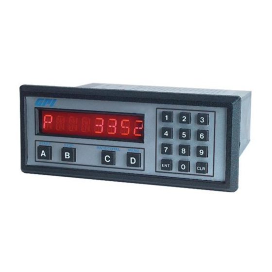
The Batcher is a programmable, microprocessor based unit which provides batch control, monitors flow
rate and controls the flow of processing liquids. Start/Stop controls can be used in conjunction with
prewarn and final relays to provide valve actuation or pump control. An optional configuration offers
streamlined preset adjustments, remote Start, Stop & Reset, and weighted averaging.
Features
Start/Stop Buttons & Remote Inputs
Separate 8 Digit K-Factors For Rate & Total
Accepts Pulse Inputs
Displays Rate, Total and Grand Total
Security Lockout with Missing Pulse Detection
Scaled Pulse Output
2 Setpoints For Two Stage Valve Control
NEMA 4X (IP65) Front Panel
Application
The unit is normally used for batch control or inventory tracking. The display may be toggled between
batch, rate, and grand total. A programmable K-factor makes keying-in engineering units easy. The unit
accepts pulse or contact closure inputs and provides two separate preset controls.
Principle of Operation
The batcher receives an input from a pulse producing flowmeter through a sensor. The user programs
the batcher to condition the incoming pulses signal and compute the batch flow and flow rate. A wide
variety of different functions can then be performed based on the programmed configurations such as
start/stop functions, totalizing, and/or flow rate monitoring.
99878 05/20/03
GBT
GBT Series Technical Manual
Advertisement
Table of Contents
Troubleshooting

Summary of Contents for GPI GBT 110
- Page 1 Installation and Operating Manual Description The Batcher is a programmable, microprocessor based unit which provides batch control, monitors flow rate and controls the flow of processing liquids. Start/Stop controls can be used in conjunction with prewarn and final relays to provide valve actuation or pump control. An optional configuration offers streamlined preset adjustments, remote Start, Stop &...
- Page 2 SAFETY INSTRUCTIONS The following instructions must be observed. • This instrument was designed and is checked in accordance with regulations in force EN 60950 (“Safety of information technology equipment, including electrical business equipment”). A hazardous situation may occur if this instrument is not used for its intended purpose or is used incorrectly.
-
Page 3: Table Of Contents
CONTENTS 1. INTRODUCTION 1-1 General Description ....................1 1-2 Typical Application ....................1 1-3 Principles of Operation .................... 1 1-4 STD PRE and EZ PRE Operation Modes ............... 3 1-5 Specifications ......................4 1-6 Dimensions ......................5 2. INSTALLATION 2-1 Receipt of Equipment ....................6 2-2 Return Shipment ..................... - Page 4 CONTENTS 5. OUTPUTS 5-1 Frequency Output ....................24 5-2 Control Outputs ..................... 25 6. TROUBLE SHOOTING AND MAINTENANCE GUIDE 6-1 Warning Messages....................26 6-2 Troubleshooting ..................... 27 6-3 Removing The Case ..................... 28 6-4 Maintenance ......................28 7. CALCULATING THE K FACTORS 7-1 General .........................
-
Page 5: Introduction
SECTION 1 INTRODUCTION 1-3 Principles of Operation Presets 1-1 General Description When the start button is pushed, two relays engage simultaneously to start flow. When Featuring 8 digits of bright, .55 inch, alphanumeric the prewarn number is reached, one relay display, the GBT can accept up to 20,000 pulses drops out. - Page 6 1-3 Principles of Operation (continued) Counter Frequency out The maximum count is 99999999. In the The Batcher generates a pulse out for each setup mode choose "RO" (Reset to Zero) for factored count. An NPN transistor output (Pin adding (count up) operation or "SP" (Set to 2), can drive external devices at rates of 10, Preset) for subtracting (count down) opera- 200, 2000 or 20000 counts per second as se-...
-
Page 7: Std Pre And Ez Pre Operation Modes
1-4 STD PRE and EZ PRE Operation Modes STD PRE and EZ PRE Operation Modes The batcher software allows the user to choose between STD PRE (Standard Preset) and EZ PRE (Easy Preset) operation modes. STD PRE operation is well suited for batch amounts that do not change, since the program mode must be entered to change the preset and the batch count must be cleared before starting a new batch. -
Page 8: Specifications
1-5 Specifications Reset Housing: Front push button: "CLR" resets displayed High impact plastic case with NEMA 4X front number and control output. panel. Remote Input (Terminal 5): Open or 0 to 1 VDC (low), 3 to 30 VDC (high), 10K ohm input Dimensions: impedance to ground. -
Page 9: Dimensions
1-6 Dimensions 1 2 3 4 5 6 7 8 9 0 1 2 3 4 5 6 7 8 9 0 1 2 3 4 5 6 7 8 9 0 1 2 1 2 3 1 2 3 4 5 6 7 8 9 0 1 2 3 4 5 6 7 8 9 0 1 2 3 4 5 6 7 8 9 0 1 2 1 2 3 1 2 3 4 5 6 7 8 9 0 1 2 3 4 5 6 7 8 9 0 1 2 3 4 5 6 7 8 9 0 1 2 1 2 3 3.31 1 2 3 4 5 6 7 8 9 0 1 2 3 4 5 6 7 8 9 0 1 2 3 4 5 6 7 8 9 0 1 2 1 2 3... -
Page 10: Installation
SECTION 2 INSTALLATION 2-1 Receipt of Equipment 2-4 Electrical Connections (Reference Figures 2-1 to 2-3) When the equipment is received, the outside packing case should be checked for damage All connections are completed at terminal incurred during shipment. If the packing case is blocks located at the rear of the case. -
Page 11: Wiring Connections And Diagrams
2-5 Wiring Connections and Diagrams 2-5 Wiring Connections and Diagrams 1 • NOT USED 2 • SCALED OUTPUT (OPEN COLLECTOR) 3 • NOT USED 4 • INPUT (PULSE) 5 • STOP / RESET INPUT 6 • NOT USED 7 • NOT USED 8 •... -
Page 12: Front Panel Operation
Weighted Averaging 3-1 Front Panel Operation The batcher software includes weighted averaging of the rate display. Weighted averaging is not available on units with 16 Point Linearization. Weighted averaging can be used to create a more stable display when the rate input is fluctuating. A START STOP RATE/TOTAL... -
Page 13: Programming
3-2 Programming 3-3 K-Factor Programming (See Programming Flow Chart, Page 10) Overview: The K-Factor is usually provided in pulses per unit, This Section of the manual provides an outline of and will have to be modified before entering it into programming procedures for the batcher software the unit. -
Page 15: How To Program
3-5 How to Program 3-6 Frequently Asked Questions About Setting Up The Batcher The initial programming of the unit is accom- Q. Is there any way to backspace if the wrong plished by first depressing the MENU button. button is hit by accident? After pressing the MENU button once, A. -
Page 16: Setup Procedure For The Batcher
3-7 Setup Procedure For The Batcher MENU ITEM 1 PRESET PRESS DISPLAY PRESET ↓ ↓ ↓ ↓ ↓ Menu Button. Flashing PRESET number. Enters Preset Routine. 0 Flashes. Clears out existing PRESET. 1 2 3 4 1234 PRESET Flashes. Sample Preset. Last count, unit now in run mode. - Page 17 3-7 Setup Procedure For The Batcher (continued) MENU ITEM 3 PRE TYP This menu item is used to set up the Preset Type. PRESS DISPLAY PRESET ↓ ↓ ↓ ↓ ↓ PREWARN ↓ ↓ ↓ ↓ ↓ PRE TYP ↓ ↓ ↓ ↓ ↓ STD PRE ↓...
- Page 18 3-7 Setup Procedure For The Batcher (continued) MENU ITEM 4 COUNT (continued) PRESS DISPLAY R0 ↓ ↓ ↓ ↓ ↓ SP ↓ ↓ ↓ ↓ ↓ Store new K Factor. RO is Reset to zero. SP is Reset to Preset. This selection determines whether the unit counts up or counts down.
- Page 19 3-7 Setup Procedure For The Batcher (continued) MENU ITEM 5 RATE Setting the Ratemeter PRESS DISPLAY PRESET ↓ ↓ ↓ ↓ ↓ PREWARN ↓ ↓ ↓ ↓ ↓ PRE TYP ↓ ↓ ↓ ↓ ↓ COUNT↓ ↓ ↓ ↓ ↓ RATE↓...
- Page 20 3-7 Setup Procedure For The Batcher (continued) MENU ITEM 6 RATE (continued from previous page) From the previous page, we are in the SIG FIG setting portion of the Ratemeter setup Menu. PRESS DISPLAY SIG FIG ## Store new WINDOW. SIG FIG indicates how many meaningful digits are shown.
- Page 21 3-7 Setup Procedure For The Batcher (continued) MENU ITEM 6 LOCKOUT This menu item uses a 4 digit security code to prevent unwanted changes in the programming or improper use of the Batcher. The unit is shipped from the factory with a security setting of 00 and a lockout code of 1000.
- Page 22 3-7 Setup Procedure For The Batcher (continued) From the previous page, we are in the CODE setting portion of the Lockout setup Menu. PRESS DISPLAY CODE Store new security time. Enters device routine to program in a 4 digit Lockout Code. The word CODE appears briefly then the current Lockout Code number is displayed.
- Page 23 3-7 Setup Procedure For The Batcher (continued) MENU ITEM 7 OUTCARD NOTE: NOT USED; This menu item reserved for future use of RS232/422 communication option. MENU ITEM 8 ALG OUT NOTE: NOT USED; This menu item reserved for future use of analog output card option.
-
Page 24: Run Mode
3-8 Run Mode 3-8.3 Locking the Unit The unit is shipped from the factory unlocked. 3-8.1 The Display To lock the unit, it must be in the Run Mode. The In the Run Mode the display will initially dis- unit is shipped from the factory with a Lockout play: Code of 1000. - Page 25 3-8 Run Mode (continued) 3-8.4 Start and Stop Operation (continued). 3-8 .4 Start and Stop Operation. The START button initiates the batch se- The Batcher is designed for batching opera- quence. Once the unit is started: tions. The batching operation is controlled by a) The display will prompt the operator two internal relays, Preset and Prewarn set- with the word STARTED.
-
Page 26: Internal Operation
3-9 Internal Operation SECTION 4 INPUTS 3-9.1 Digital Inputs and Computations 4-1 Digital Pulse Inputs (Terminal 4) The 3-30 Volt input signal is filtered electroni- Digital Pulse Inputs: The input board is a cally separate board that is plugged into the mother board just behind the display. - Page 27 4-1 Digital Pulse Inputs (continued) 4-1.3 Reset Input (Terminal 5) 4-1.1 STANDARD: High Impedance (Terminal Identical to the Standard, High Impedance In- put with one exception. The input speed is Has a 10 K Ohm pull down resistor to ground fixed for a minimum pulse width of 5 msec.
-
Page 28: Dc Power Inputs
4-2 DC Power Inputs (Terminals 12, 14) SECTION 5 OUTPUTS The Batcher may be powered by an external DC The Batcher has two outputs for controlling power supply. The supply must provide 12 - 27 external devices or monitoring the rate and Volts DC and at least 280 mA of current. -
Page 29: Control Outputs
5-1.2 Internal Buffer for Frequency Output 5-2 Control Outputs An internal buffer will store up to 9,999 counts if 5-2.1 SPDT Relay Version (Standard) the scaled input generates pulses faster than When the start button is pushed, the two relays the output speed selected. -
Page 30: Trouble Shooting And Maintenance Guide
SECTION 6 TROUBLE SHOOTING AND MAINTENANCE GUIDE 6-1.3 RFFFFFFF 6-1 Warning Messages Indicates that the factored input rate has ex- 6-1.1 PREWRONG ceeded a 7 digit number. The ratemeter cannot handle numbers larger than 7 digits (i.e. Indicates that the values in Preset and Prewarn 9999999). -
Page 31: Troubleshooting
6-2 Troubleshooting 6-2.1 General Symptom: Unable to start batch. The following troubleshooting procedures have Possible Cause #1: Displayed Batch count al- been developed as an aid in locating defects. ready exceeds the Preset value. Not every possible problem has been listed, but Test Procedure: Check Preset value against a general isolation procedure for tracking down the displayed value. -
Page 32: Removing The Case
6-3 Removing the Case 6-4Maintenance To install or change the input or data interface The Batcher does not require any "Routine cards, the case must be removed. Remove Maintenance" by the user. If a problem all power before opening the case. CMOS should occur, and all troubleshooting proce- logic is used so observe standard precautions dures have been exhausted, contact your lo-... -
Page 33: Calculating The K Factors
7-2 Calculating the K Factors. Step 3. Enter the Count K Factor. (See The following steps are the recommended Section 3-3, Menu Item 3). procedure for calculating the K Factors. Take your time and go through the procedure Step 4. Modify the Count K Factor to reflect slowly at first. -
Page 34: Programming Worksheet
8 Programming Worksheet Model # _____________________________ Serial # _____________________________ Unit # ______________________________ PRESET _ _ _ _ _ _ _ _ OUTput FREQuency 20000 PREWARN _ _ _ _ _ _ _ _ 2000 PREset TYPe EZ PRE STD PRE COUNTer K-FACTOR _ _ _ _ _ _ _ _ Reset to 0... - Page 35 ALL OTHER WARRANTIES, EXPRESSED OR IMPLIED, ARE EX- CLUDED, INCLUDING BUT NOT LIMITED TO THE IMPLIED WARRAN- TIES OF MERCHANTABILITY AND FITNESS FOR A PARTICULAR PUR- POSE. Ordering Ordering Information GBT 110 - 110 VAC Powered GBT 220 - 220 VAC Powered...
Need help?
Do you have a question about the GBT 110 and is the answer not in the manual?
Questions and answers