Advertisement
Quick Links
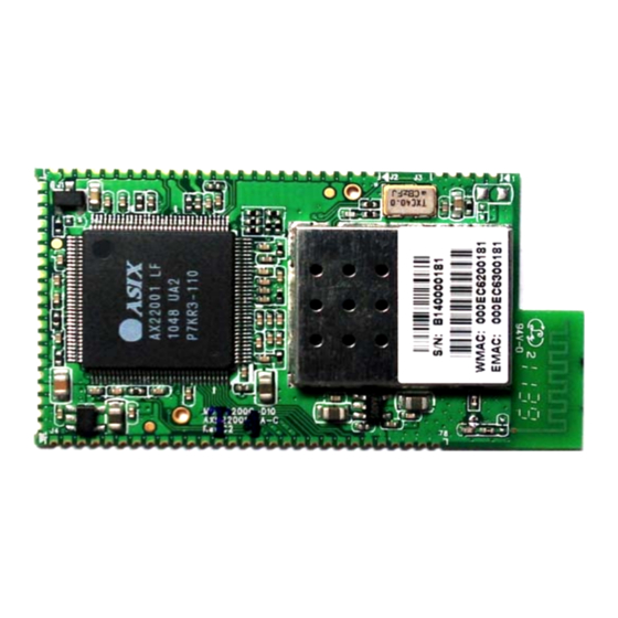
Model Name: AXM22001-2A-C
Key Features
Integrated 2.4GHz, IEEE 802.11b/g compatible
WiFi connectivity
Integrated PCB antenna
Max outdoor range up to 300m (984 ft.), line of
sight
Supports operation in Infrastructure or Ad-Hoc
(IBSS) network topology
Supports 802.11i security: WEP-64/128, TKIP
(WPA-PSK) and AES (WPA2-PSK)
Dual 8-bit 1T 8051/80390 CPU @ 80MHz
1MB shared Flash memory for MCPU and
WCPU program code and configuration data
storage
64KB data memory for MCPU
4 UART interfaces
High Speed SPI interface (master or slave
mode)
I2S or PCM interface
Local Bus host interface (master or slave mode)
MII or RMII interface
I2C interface
Up to 32 GPIOs (4 GPIO ports of 8 bits each)
Supports real-time clock, with option to use
independent power supply from lithium battery
Supports TCP, UDP, ICMP, IGMP, IPv4,
DHCP, BOOTP, ARP, DNS, SMTP, SNTP,
UPnP, PPPoE and HTTP in software
Supports network boot over Ethernet or WiFi
using BOOTP and TFTP
Single operating voltage: 3.3V typical
Board size: 51.0mm x 28.0mm x 4.5mm
surface mountable module
Applications
Serial to WiFi Device Server
WiFi Speaker
WiFi Remote Control/Monitor
Ethernet to WiFi Bridge
Zigbee to WiFi Bridge
WiFi Network Camera
WiFi RFID
SPI to WiFi Bridge
TCP/IP and WLAN Offload Co-processor
WiFi Internet Radio
Copyright © 2011 ASIX Electronics Corporation. All rights reserved.
IEEE 802.11b/g WiFi Module Board User's Guide
The AXM22001-2A-C is a 2.4GHz 802.11b/g WiFi module
board which integrates AX22001 and Airoha AL2230S RF
transceiver on board to provide a complete WiFi module
solution with various user or host interfaces supported. The
AXM22001-2A-C is a surface mountable module with
castellated mounting holes which offers smaller-form-factor,
lower-cost, pre-calibrated RF front-end and pre-certified WiFi
module board to free the user from RF and antenna design
tasks and regulatory compliance testing, ultimately providing
quicker time to market. The user can design his host board with
desired function and interface circuits and assemble it with the
AXM22001-2A-C WiFi module board through the castellated
mounting holes.
Document No: AXM22001-2A-C/V1.01/11/07/11
1
AXM22001-2A-C
Advertisement

Summary of Contents for ASIX AXM22001-2A-C
- Page 1 Dual 8-bit 1T 8051/80390 CPU @ 80MHz 1MB shared Flash memory for MCPU and WCPU program code and configuration data storage The AXM22001-2A-C is a 2.4GHz 802.11b/g WiFi module 64KB data memory for MCPU board which integrates AX22001 and Airoha AL2230S RF 4 UART interfaces...
- Page 2 Pinout Diagram of Castellated Mounting Holes 3V3_PAS 3V3_PAS 3V3_RF 3V3_RF MISO XTL32KO MOSI XTL32KI SCLK VCC18A_RTCI RSTO_N LB_CLK WLED SYSCK_SEL INT1 XDATA1 INT0 XDATA2 TXD0 XDATA4 RXD0 XDATA5 XDATA6 RST_N Figure 1. Module pinout Copyright © 2011 ASIX Electronics Corporation. All rights reserved.
- Page 3 P12 / LA2 / WST / TX_ER signals J1.13 P13* P13 / LA3 / DATAT / COL signals J1.14 I2C serial clock J1.15 I2C serial data J1.16 Ground J1.17 3.3V power input J1.18 3.3V power input J1.19 Ground Copyright © 2011 ASIX Electronics Corporation. All rights reserved.
- Page 4 * These pins are multi-function pins in AX22001. Please refer to Section 3.1.3 “Multi-function Pin Setting (0x07 ~ 0x02)” on AX22001 datasheet to configure proper pin functions for your AX22001 application. Please feel free to contact ASIX Electronics Technical Support (support@asix.com.tw) to receive AXM22001-2A-C WiFi module board schematic and BOM file for details.
-
Page 5: Board Dimensions
AXM22001-2A-C IEEE 802.11b/g WiFi Module Board User’s Guide Board Dimensions The AXM22001-2A-C is a surface mountable module with castellated mounting holes on three sides. Below shows the module dimensions. 28.0mm 51.04mm Figure 2. Module Dimension Copyright © 2011 ASIX Electronics Corporation. All rights reserved. - Page 6 IEEE 802.11b/g WiFi Module Board User’s Guide Host PCB Footprint Below shows the recommended host PCB footprints for the module. The AXM22001-2A-C module has an integrated PCB antenna which requires the host PCB to maintain certain copper keep-out area as shown below, for best antenna performance.
- Page 7 IEEE 802.11b/g WiFi Module Board User’s Guide Module Reflow Profile Conveyor Speed: 70 cm/min Zone #AD1 #AD2 #AD3 #AD4 #AD5 #AD6 #AD7 #AD8 Upper Limit(℃) Lower Limit(℃) Time (S) Figure 4. Module Reflow Copyright © 2011 ASIX Electronics Corporation. All rights reserved.
-
Page 8: Pcb Antenna
Figure 5. Module in horizontal antenna pattern Figure 6. Module in vertical antenna pattern Copyright © 2011 ASIX Electronics Corporation. All rights reserved. -
Page 9: Regulatory Approval
The AXM22001-2A-C module has acquired the regulatory approvals for modular devices in the United States. Modular approval allows the user to mount the AXM22001-2A-C module inside his own final product and needn’t the regulatory testing, if no changes or modifications to the module circuitry. Any changes or modifications will cause the user to lose his authority to operate the equipment. -
Page 10: Helpful Web Sites
If the AXM22001-2A-C module is used in a portable application (i.e., the antenna is less than 20 cm from persons during operation), the integrator is responsible for performing Specific Absorption Rate (SAR) testing in accordance with FCC rules 2.1091. - Page 11 Helpful Web Sites: Radio and Telecommunications Terminal Equipment (R&TTE):http://ec.europa.eu/enterprise/rtte/index_en.htm European Conference of Postal and Telecommunications Administrations (CEPT):http://www.cept.org/ European Telecommunications Standards Institute (ETSI): http://www.etsi.org/ European Radio Communications Office (ERO): http://www.ero.dk/ Copyright © 2011 ASIX Electronics Corporation. All rights reserved.
Need help?
Do you have a question about the AXM22001-2A-C and is the answer not in the manual?
Questions and answers