Table of Contents
Advertisement
Quick Links
E71-314
Sierra™
User's Manual
THIS DOCUMENT IS THE SOLE PROPERTY OF ASTRONICS CONNECTIVITY SYSTEMS & CERTIFICATION ("ASTRONICS CSC") AND SHALL
NOT BE REPRODUCED, COPIED OR ISSUED AS THE BASIS OF MAINTENANCE OR SALE OF APPARATUS WIHTOUT PERMISSION OF
ASTRONICS CSC.
804 S. Northpoint Blvd. | Waukegan, IL 60085
+1.847.244.4500
THIS DOCUMENT HAS BEEN ELECTRONICALLY SIGNED IN ASTRONICS CSC'S PLM
SYSTEM. ALL ELECTRONIC SIGNATURES ARE ON FILE IN THE PLM SYSTEM AND ARE
FULLY AUDITABLE.
Astronics CSC
Inflight Entertainment and Connectivity Systems
Document Control RELEASED
astronics.com
Advertisement
Table of Contents

Summary of Contents for Astronics Sierra E71-314
- Page 1 Astronics CSC Inflight Entertainment and Connectivity Systems THIS DOCUMENT IS THE SOLE PROPERTY OF ASTRONICS CONNECTIVITY SYSTEMS & CERTIFICATION (“ASTRONICS CSC”) AND SHALL NOT BE REPRODUCED, COPIED OR ISSUED AS THE BASIS OF MAINTENANCE OR SALE OF APPARATUS WIHTOUT PERMISSION OF ASTRONICS CSC.
- Page 2 EUROPEAN UNION COMPLIANCE STATEMENT Hereby, Astronics CSC, declares that this Sierra™ Portable Inflight Entertainment (IFE) System is in compliance with the essential requirements and other relevant provisions of Directive 2014/53/EU. The full text of the EU declaration of conformity is available at the following internet address: https://www.astronics.com/subsidiary?subsidiaryItem=astronics%20connectivity%20systems%20and%20...
-
Page 3: Table Of Contents
Mean Time to Repair (MTTR) ..................... 54 11.4 Failure Detection and Fault Isolation ..................54 11.5 Production Testing ........................54 Support and Service ........................55 Page | 3 Revision Date April 30, 2020 || Document Number UM-E71-314 || Rev B astronics.com... - Page 4 Technical Support ........................55 12.2 Returning Defective Equipment ....................55 Table of Tables Table 1-1: Astronics CSC Support Documentation ..................6 Table 1-2: Aruba Support Documentation ....................6 Table 1-3: Industry Standards ........................7 Table 3-1: Sierra Kit Specific Drawing Information ..................15 Table 3-2: Sierra Orderable Part Numbers ....................
- Page 5 Figure 10-2: Sierra I/O Front View ......................49 Figure 10-3: Sierra Side View ........................49 Figure 10-4: Sierra Rear View ........................50 Figure 10-5: Sierra Bottom View ........................ 50 Page | 5 Revision Date April 30, 2020 || Document Number UM-E71-314 || Rev B astronics.com...
-
Page 6: User Information
1 User Information This User’s Manual describes the features supported by Astronics CSC third generation streaming portable Inflight Entertainment (IFE) system, branded as Sierra and provides detailed instructions for setting up and configuring the Sierra IFE portable system. This guide is intended for administrators who configure and use Sierra. -
Page 7: Industry Standards
Astronics CSC will not be responsible for any defects or damages to other products not supplied by Astronics CSC that are caused by a faulty Astronics CSC product. -
Page 8: Important Safety Instructions
Sierra contains the following Intentional Radiators: Wi-Fi Transceiver FCCID: 2AL4H-E71314 IC: 22737-E7131901 Aux Wi-Fi Transceiver FCCID: PD98265NG IC: 1000M-8265NG Cellular Transceiver FCCID: N7NEM75 IC:2417C-EM75S Page | 8 Revision Date April 30, 2020 || Document Number UM-E71-314 || Rev B astronics.com... - Page 9 (847) 244-4500 www.astronics.com We, Astronics CSC, 804 S. Northpoint Blvd. Waukegan, IL 60085, declare under our sole responsibility that the product E71-314 Sierra™ complies with Part 15 Subpart B of FCC CFR47 Rules. This device complies with part 15 of the FCC Rules. Operation is subject to the following two conditions: (1) This device may not cause harmful interference, and (2) this device must accept any interference received, including interference that may cause undesired operation.
- Page 10 (c.-à-d., qu'ils ont la priorité) pour les bandes 5250-5350 MHz et 5650-5850 MHz et que ces radars pourraient causer du brouillage et/ou des dommages aux dispositifs LAN-EL. Page | 10 Revision Date April 30, 2020 || Document Number UM-E71-314 || Rev B astronics.com...
- Page 11 2.2.3 European Union (EU) Compliance Information 2.2.3.1 Radio Equipment Directive Hereby, Astronics CSC declares that this Sierra™ Portable Inflight Entertainment (IFE) System is in compliance with the essential requirements and other relevant provisions of Directive 2014/53/EU. The full text of the EU declaration of conformity is available at the following internet address: https://www.astronics.com/certificates?subsidiaryName=Astronics%20Connectivity%20Systems%20...
-
Page 12: Battery Safety
In compliance with the Waste Electrical and Electronic Equipment (WEEE) directive, return this product to a local recycling center, the original dealer, or supplier at the end of life. Otherwise, return the device to the following office: Astronics CSC 804 S. Northpoint Blvd. Waukegan, IL 60085 (847) 244-4500 www.astronics.com... - Page 13 Retain the original product literature for future reference. • There is a risk of explosion if the battery is replaced by an incorrect type. Page | 13 Revision Date April 30, 2020 || Document Number UM-E71-314 || Rev B astronics.com...
-
Page 14: Introduction
3 Introduction 3.1 Product Description Sierra is Astronics-CSC third generation streaming portable Inflight Entertainment (IFE) system designed to install in the overhead compartment of commercial aircraft. Sierra is primarily a battery- operated alternative to a fixed IFE installation. Sierra is capable of multi-user media streaming of audio, video-on-demand, digital magazine content, and much more. -
Page 15: Hardware Architecture
4G/LTE cellular radio. Automatically disables cellular modem based on aircraft ADSB data. • Audio/Video content can be paused remotely via detecting a PA announcement • Disables itself automatically in the event of an emergency decompression Page | 15 Revision Date April 30, 2020 || Document Number UM-E71-314 || Rev B astronics.com... -
Page 16: Key Hardware Components
TPM per TPM 2.0 PA Pause Optionally can automatically pause streaming content in the event of a PA announcement. Note: Requires a PA Pause Module, Astronics CSC P/N E71-500-01, installed in the aircraft. Front Removable: Up to 2 TB SSD Mass Storage ... -
Page 17: Figure 3-1: Sierra System Block Diagram
Rear Pnl PCBA Ethernet Rear RJ45 Panel Ext DIN Pwr Aircraft Blade Connector Pwr Connector Access Point 802.11ac/g/b/n Figure 3-1: Sierra System Block Diagram Page | 17 Revision Date April 30, 2020 || Document Number UM-E71-314 || Rev B astronics.com... -
Page 18: Orderable Part Numbers
3.4 Orderable Part Numbers Table 3-2: Sierra Orderable Part Numbers Astronics CSC P/N Description Kit, Sierra, Removable SSD E71-314-XXX E71-319-01 Sierra Base Unit Assembly RSSD Module E54-576-XX AHM250PS19 External Power Module with Cable E71-500-01 PA Pause Assembly Li-Ion Battery (purchase directly from RRC Power... -
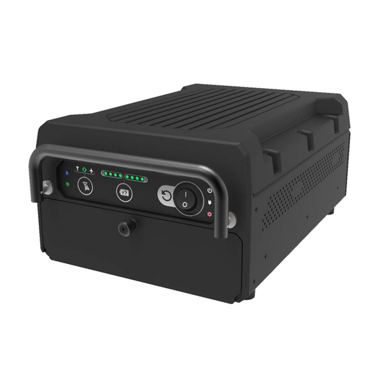
Page 19: Powering Up
Once power is connected via batteries or external power source, turn the POWER switch to ‘ON’ position as shown. Figure 4-2: Power On/Off Switch and Power Indicator Page | 19 Revision Date April 30, 2020 || Document Number UM-E71-314 || Rev B astronics.com... -
Page 20: Connecting To Sierra
Flow Control 115200 8 bit none 1 bit none 9600 8 bit none 1 bit none Cell Modem 9600 8 bit none 1 bit none Page | 20 Revision Date April 30, 2020 || Document Number UM-E71-314 || Rev B astronics.com... -
Page 21: Ssh
Sierra comes configured with the following ATP SSIDs, where xxxxxx is replaced with the unit’s serial number. The password for both is: 12345678 • xxxxxxw2p4ghz • xxxxxxw5ghz Page | 21 Revision Date April 30, 2020 || Document Number UM-E71-314 || Rev B astronics.com... -
Page 22: Wap Configuration
The min/max power settings of the 5 GHz radio have been set 6dbm higher than the 2.4 GHz radio. This accounts for the additional free space path loss and smaller receiver aperture associated with the higher frequencies. Page | 22 Revision Date April 30, 2020 || Document Number UM-E71-314 || Rev B astronics.com... -
Page 23: Connecting Using Aruba's Web-Based Gui
6. Usage Trends – Shows all the clients and throughput generated by all the clients on this cluster. Clicking on the + or – signs in the band or section title bar will expand or collapse that band or section. Page | 23 Revision Date April 30, 2020 || Document Number UM-E71-314 || Rev B astronics.com... -
Page 24: Figure 6-2: The Six Sections Of The Aruba Instant Main Gui Page
Blue text items or Green icons will display details of that item. Figure 6-2: The Six Sections of the Aruba Instant Main GUI Page Page | 24 Revision Date April 30, 2020 || Document Number UM-E71-314 || Rev B astronics.com... -
Page 25: Figure 6-3: System Username And Password Dialog Box
The system username and password can be changed from the Admin tab of the System dialog box, as show in Figure 6-3. Figure 6-3: System Username and Password Dialog Box. Page | 25 Revision Date April 30, 2020 || Document Number UM-E71-314 || Rev B astronics.com... -
Page 26: Figure 6-4: Additional Network Information
The Usage Trends section provides both client, and throughput information for the selected wireless network. in Figure 6-6, clicking on the throughput graph opens a popup window with a more detailed graph. Page | 26 Revision Date April 30, 2020 || Document Number UM-E71-314 || Rev B astronics.com... -
Page 27: Figure 6-6: The Wireless Network Usage Trends Section
Selecting one of these text items will display radio specific details as shown in Figure 6-8. Figure 6-7: Information Band Display for Selected Access Point Page | 27 Revision Date April 30, 2020 || Document Number UM-E71-314 || Rev B astronics.com... -
Page 28: Figure 6-8: Radio Specific Details
Figure 6-9 shows the details of the Clients section. You can click on a client’s name to display the details for that client in the Information band as shown in Figure 6-10. Figure 6-9: Clients Section Page | 28 Revision Date April 30, 2020 || Document Number UM-E71-314 || Rev B astronics.com... -
Page 29: Figure 6-10: Client Details
Figure 6-10: Client Details Page | 29 Revision Date April 30, 2020 || Document Number UM-E71-314 || Rev B astronics.com... -
Page 30: Wlan Setup
4. The last stage is the settings for the firewall with the user rights. These stages are shown below in Figure 7-1. Figure 7-1: The Four Stages to Creating an SSID Page | 30 Revision Date April 30, 2020 || Document Number UM-E71-314 || Rev B astronics.com... -
Page 31: Figure 7-2: The Wlan Settings Tab Of The New Wlan Dialog Box
The WLAN Settings tab is where you select the type of SSID you want to create and name the SSID, as shown below in Figure 7-2. Figure 7-2: The WLAN Settings Tab of the New WLAN Dialog Box Page | 31 Revision Date April 30, 2020 || Document Number UM-E71-314 || Rev B astronics.com... -
Page 32: Figure 7-3: The Vlan Tab Of The New Wlan Dialog Box
The Access Points will be providing DHCP for any wireless clients that connect to this SSID. • The SSID and IAPs will source NAT all client traffic onto the wire. Page | 32 Revision Date April 30, 2020 || Document Number UM-E71-314 || Rev B astronics.com... -
Page 33: Figure 7-4: Configuring An External Radius Server
Selecting the Enterprise level allows you to configure an external RADIUS authentication server, as shown below in Figure 7-4. Figure 7-4: Configuring an External RADIUS Server Page | 33 Revision Date April 30, 2020 || Document Number UM-E71-314 || Rev B astronics.com... -
Page 34: Figure 7-5: Configuring Firewall Rules
In the Security tab, select External for Splash Page Type, and then select the Edit button to edit the default Captive Portal Profile as shown below in Figure 7-6. Page | 34 Revision Date April 30, 2020 || Document Number UM-E71-314 || Rev B astronics.com... -
Page 35: Figure 7-6: External Captive Portal Settings
Deny any to any Place the following lines in the body of your index.html file which will automatically authenticate your guests. <form> <input type=”hidden” id=”authtext” value=Guest_Authenticated”> </form> Page | 35 Revision Date April 30, 2020 || Document Number UM-E71-314 || Rev B astronics.com... -
Page 36: User Interface
External Power LED Software programmable. Status LED A momentary press displays the state-of-charge of each battery through an array of LEDs. Battery Strength Button Page | 36 Revision Date April 30, 2020 || Document Number UM-E71-314 || Rev B astronics.com... - Page 37 Illuminates when Bluetooth is enabled and paired to an external Bluetooth Status LED discrete I/O device, e.g. the PA Pause module. Illuminates when the Aruba Wi-Fi is enabled. Wi-Fi Status LED Page | 37 Revision Date April 30, 2020 || Document Number UM-E71-314 || Rev B astronics.com...
-
Page 38: Battery Status Indicator
To access the battery bays, SIM card, SSD, and maintenance connectors behind the battery door, turn the knob (shown in Figure 8-3) counter-clockwise then open the battery door downward. Page | 38 Revision Date April 30, 2020 || Document Number UM-E71-314 || Rev B astronics.com... -
Page 39: Figure 8-3: Battery Door
• USB-C for serial console access to the CPU and access point • USB 3.0 port • SIM card slot • Two battery bays Page | 39 Revision Date April 30, 2020 || Document Number UM-E71-314 || Rev B astronics.com... -
Page 40: Figure 8-4: Hardware Interface Behind The Battery Door
Figure 8-4: Hardware Interface behind the battery door Page | 40 Revision Date April 30, 2020 || Document Number UM-E71-314 || Rev B astronics.com... -
Page 41: Figure 8-5: Removable Ssd Ejection Instructions
8.4.1 SSD Removal Instructions Figure 8-5: Removable SSD Ejection Instructions Page | 41 Revision Date April 30, 2020 || Document Number UM-E71-314 || Rev B astronics.com... -
Page 42: Figure 8-6: Removable Ssd Installation Instructions
Note: The SSD Block Plate is intended as a theft deterrent device. Usage is optional. Figure 8-6: Removable SSD Installation Instructions Page | 42 Revision Date April 30, 2020 || Document Number UM-E71-314 || Rev B astronics.com... -
Page 43: Performance Data
Combining the patterns of both antennas per radio, the peak gain of the average (effective) pattern is 2.1dBi in 2.4GHz and 4.6dBi in 5GHz. **The aggregate EIRP is limited to 20dBm (100mW). Page | 43 Revision Date April 30, 2020 || Document Number UM-E71-314 || Rev B astronics.com... -
Page 44: Table 9-2: Rf Performance Table
Note: Table shows the maximum hardware capabilities of the AP (excluding antenna and MIMO/MRC gain). Actual maximum transmit power may be limited below these numbers to ensure compliance with local regulatory requirements. Page | 44 Revision Date April 30, 2020 || Document Number UM-E71-314 || Rev B astronics.com... -
Page 45: Country Codes
Laos People's Cameroon Democratic Republic Serbia Serbia and Canada Latvia Montenegro Chad Lebanon Singapore Chile Liberia Slovak Republic Country Code Country Code Country Code Page | 45 Revision Date April 30, 2020 || Document Number UM-E71-314 || Rev B astronics.com... - Page 46 Nepal Uzbekistan French Guiana Netherlands Vatican City French Polynesia New Caledonia Venezuela French Southern Territories New Zealand Vietnam Gambia Nicaragua Yemen Georgia Niger Zimbabwe Page | 46 Revision Date April 30, 2020 || Document Number UM-E71-314 || Rev B astronics.com...
-
Page 47: Technical Data
Modified the DO-160G, Section 4.5.4, Category A1, Operating High Temperature, limit from +55 C to C, as designed and described in the product specification, PS-E71-314. Modified to perform only one cycle of the temperature profile. Page | 47 Revision Date April 30, 2020 || Document Number UM-E71-314 || Rev B astronics.com... -
Page 48: Mechanical Design And Dimensions
The Sierra’s internal chassis, circuit cards, wiring and cabling, and other major components are mounted and secured to provide maximum protection against imposed shock and vibration. 10.2.1 Top View Figure 10-1: Sierra Top View Page | 48 Revision Date April 30, 2020 || Document Number UM-E71-314 || Rev B astronics.com... -
Page 49: Figure 10-2: Sierra I/O Front View
10.2.2 I/O Front View Figure 10-2: Sierra I/O Front View 10.2.3 Side View Figure 10-3: Sierra Side View Page | 49 Revision Date April 30, 2020 || Document Number UM-E71-314 || Rev B astronics.com... -
Page 50: Figure 10-4: Sierra Rear View
10.2.4 Rear View Figure 10-4: Sierra Rear View 10.2.5 Bottom View Figure 10-5: Sierra Bottom View Page | 50 Revision Date April 30, 2020 || Document Number UM-E71-314 || Rev B astronics.com... - Page 51 Input Voltage: 18V nominal • AHM250PS19 Supply Powered (with batteries charging): Power Consumption: 178.0W nominal, 179.9W max Current Draw: 9.37A nominal, 9.47A max Input Voltage: 19V nominal Page | 51 Revision Date April 30, 2020 || Document Number UM-E71-314 || Rev B astronics.com...
- Page 52 Rear (G6) = 1.00” Installations violating the above air gap spacing must be approved by Astronics CSC engineering. There are no minimum installation distances between Sierras. The maximum distance shall be determined by aircraft type and configuration and content (e.g. throughput considerations).
-
Page 53: Workmanship
The batteries comply with UL2054:2011 / UL1642:2009 and IEC62133:2012. Page | 53 Revision Date April 30, 2020 || Document Number UM-E71-314 || Rev B astronics.com... -
Page 54: Reliability And Maintainability
RIAC 217+ (AIC, +30°C, 65% duty cycle, 2190 cycles per year). 11.2 Maintainability The Sierra is considered an LRU and is repairable only by Astronics CSC or an authorized repair facility. Periodic maintenance of the Sierra is not required. -
Page 55: Support And Service
RMA number. The Buyer accepts responsibility for all freight charges for the return of goods to the Astronic CSC designated facility. Astronics CSC will pay return freight charges back to the Buyer's location in the event that the equipment is repaired or replaced within the warranty period stipulated herewith. - Page 56 Section 2.2: Updated Wi-Fi Transceiver FCC 04-30-2020 Section 2.2.3.1: Updated the EU declaration of conformity URL. Added a statement Volodya Vandakurov Mike O’Connor regarding restriction to indoor use. Page | 56 Revision Date April 30, 2020 || Document Number UM-E71-314 || Rev B astronics.com...
Need help?
Do you have a question about the Sierra E71-314 and is the answer not in the manual?
Questions and answers