Table of Contents
Advertisement
Quick Links
Advertisement
Table of Contents

Subscribe to Our Youtube Channel
Summary of Contents for ARB RD203
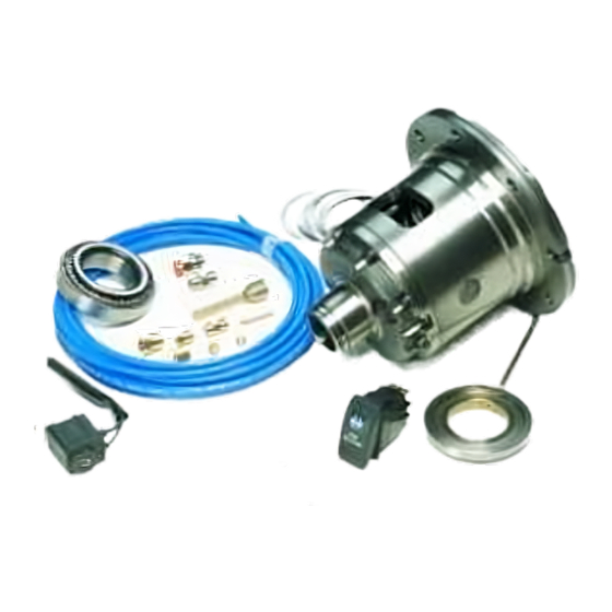
- Page 1 ISUZU IFS, 17 SPLINE AIR OPERATED LOCKING DIFFERENTIAL INSTALLATION GUIDE...
- Page 2 No liability is assumed for damages resulting in the use of the information contained herein. ARB Air Locker Locking Differentials and Air Locker are trademarks of ARB Corporation Limited. Other product names used herein are for identification purposes only and may be trademarks of their respective owners.
-
Page 3: Table Of Contents
1 Introduction 1.1 Pre-Installation Preparation 1.2 Tool-Kit Recommendations 2 Removing the Existing Differential 2.1 Vehicle Support 2.2 Differential Fluid Drain 2.3 Removal of the Axles and Differential 2.4 Marking the Bearing Caps 2.5 Checking the Current Backlash Amount 2.6 Spreading the Differential Housing 3 Bench Measurement 3.1 Measurement for Pre-Load Shimming 3.2 Calculation &... -
Page 5: Introduction
Although your ARB Air Locker comes complete with all the step by step instructions you will need to supplement your vehicle manufacturer’s service manual and install your new differential, ARB recommends that you have your Air Locker installed by a trained professional. -
Page 6: Tool-Kit Recommendations
An automotive bearing puller (e.g. ARB Bearing Puller #0770001 or a differential carrier bearing puller. A bearing press or arbor press. A suitable shim driver (e.g. ARB Shim Driver #0770004). A soft hammer (e.g. raw hide or nylon). Supplies 1.2.2 ... -
Page 7: Removing The Existing Differential
2 Removing the Existing Differential Vehicle Support Safely secure the vehicle on a hoist. We recommend supporting the vehicle on a chassis hoist to keep the differential area at a convenient working height and to leave the wheels and axles free to be rotated and removed. -
Page 8: Marking The Bearing Caps
2 Removing the Existing Differential NOTE : Rubber oil seals can be easily damaged. Support the weight of the axle when extracting it across the edges of the seals. Remove the differential housing from the axle case and secure it to a workbench. -
Page 9: Checking The Current Backlash Amount
2 Removing the Existing Differential Checking the Current Backlash Amount IMPORTANT: This step is a precautionary measure recommended by ARB due to the fact that some aftermarket ring and pinion sets have been manufactured to run with different backlash settings than those specified by your vehicle manufacturer. -
Page 10: Spreading The Differential Housing
2 Removing the Existing Differential Spreading the Differential Housing IMPORTANT: Spreading the differential housing with a differential case spreader is a step which is critical to set up bearing pre-load when a differential is installed. Improper pre-load will result in undue bearing wear, increased stresses in the differential center, increased running noise, and ultimately, ring and pinion gear damage. -
Page 11: Bench Measurement
3 Bench Measurement Measurement for Pre-Load Shimming When fitting an ARB Air Locker, the original bearing types are used on both sides of the Air Locker, however, in order to reproduce a similar backlash and pre-load to that of your existing differential, measurements need to be taken so that the correct shim thickness can be determined for each side. - Page 12 3 Bench Measurement Using a caliper or similarly accurate measurement method (i.e., able to take accurate measurements within 0.04mm [0.0015”]), measure the distance from the bearing shoulder to the ring gear mounting face (shown as ‘A’ in Figure 5.) and record this measurement as ‘A’.
-
Page 13: Calculation & Selection Of Shims
3 Bench Measurement AIR LOCKER DIFFERENTIAL Figure 6. Calculation & Selection of Shims The thickness of the shim pack required for the Air Locker (shown as ‘D’ in Figure 6.) can now be determined by substituting the measurements taken into the following equation. A + B –... -
Page 14: Installing The Air Locker
4 Installing the Air Locker Installing the Carrier Bearings With the Air Locker well supported in an arbor press, apply a thin film of high-pressure grease to the case side bearing journal. Identify the bearings according to where each was removed from the OE diff, and allocate them to the correct sides of the Air Locker respectively. -
Page 15: Mounting The Ring Gear
4 Installing the Air Locker Mounting the Ring Gear Apply a thin film of high-pressure grease to the ring gear shoulder of the Air Locker to prevent seizing. Thoroughly clean any thread locking compound or other foreign matter from the holes of the ring gear, the threads of the ring gear bolts, and the mating surfaces of the ring gear and the Air Locker flange. -
Page 16: Drilling & Tapping The Bulkhead Port
4 Installing the Air Locker Drilling and Tapping the Bulkhead Port A port must be drilled and tapped through the differential housing to allow the seal housing tube through the housing to connect with the air line from the air compressor. IMPORTANT: Some differentials on newer Isuzu models (e.g. - Page 17 4 Installing the Air Locker Cover the drive pinion or axle tube areas with a rag to protect them from metal filings. Drill through the housing, square to the outside surface using an 11.2mm [7/16”] drill. Tap the hole from the outside using a ¼’’ NPT tapered pipe thread tap.
-
Page 18: Assembling The Differential Carrier
4 Installing the Air Locker Assembling the Differential Carrier Place the bearing cup over the bearing cone on the seal housing side (Fig 10.) AIR LOCKER DIFFERENTIAL Figure 10. Carefully install the seal housing by sliding it all the way onto the bearing journal with a gentle twisting motion until it sits flat against the adjuster nut. - Page 19 4 Installing the Air Locker Push the Air Locker hard across to the case side, and measure the gap (end float) between the seal housing and the bearing bore edge with a feeler gauge. Consult your vehicle manufacturer’s service manual to determine the carrier bearing pre-load amount specified for your vehicle.
-
Page 20: Modifying The Bearing Cap
4 Installing the Air Locker Modifying the Bearing Cap NOTE : It is very important to make sure the punch marks made on the differential housing while removing the differential are matched to the punch marks on the bearing cap. The bearing cap must be replaced exactly as it was removed. -
Page 21: Final Air Locker Assembly
4 Installing the Air Locker Final Air Locker Assembly With the seal housing removed clean all parts of the differential assembly. It is very important to make sure the bearing journal is free from any contaminants (eg: water, dirt, metal fillings, etc.) ... -
Page 22: Final Backlash Checking
4 Installing the Air Locker Final Backlash Checking Set a depth indicator on one of the ring gear teeth as in Figure 13. While supporting the pinion gear by holding the drive shaft, rotate the differential in both directions while observing the maximum variation in depth from the indicator (i.e. -
Page 23: Profiling The Seal Housing Tube
4 Installing the Air Locker Profiling the Seal Housing Tube Depending on the axle case material type, the seal housing tube is to be profiled differently. See examples below for suggested profiles that will suit your differential. Cast Iron Axle Case. - Page 24 4 Installing the Air Locker Aluminium Axle Case. Without using sharp, jagged tools such as pliers (usually your hands are the best tool for this job), bend the seal housing tube at a right angle, immediately where it protrudes through the bearing housing, and then another sharp bend upwards, at approximately 25mm from the centre line (Fig.
-
Page 25: Setting Up The Bulkhead Fitting
4 Installing the Air Locker 4.9 Setting up the Bulkhead Fitting NOTE : Use an automotive brake line tubing cutter to cut the seal housing tube. Never use a hacksaw for trimming the steel tube as this will leave metal fillings in the air system. -
Page 26: Bench Testing The Air Locker
Rotate the differential carrier by turning the pinion flange whilst applying air pressure. NOTE : An accurate way to test for air leaks is to fit a shut-off valve to an air pressure gauge. (ARB part # 0770005 shown in Fig. ). Once 620 KPA [90 PSI] is reached close the valve, disconnect the air hose, and watch to see if there is any drop in pressure. -
Page 27: Reinstalling The Axles
4 Installing the Air Locker Check that leaky fittings have been adequately tightened. Disassemble, clean threads, and reapply thread sealant if leaking persists. If a leak is found at the seal housing, carefully remove and refit. Be very careful with the O-rings and check they have not been damaged during installation. -
Page 28: Installing The Air System
Installing the Air System Mounting the Solenoid Connection to an ARB Air Compressor (Fig.20.) 5.1.1 Remove one of the 1/8” BSP plugs from its port in the compressor tank. Apply Teflon paste to the nipple (1/8” X 1/8” BSP) and insert it into the port and tighten. - Page 29 For ease of installation, quality of air supply, and a high level of dependability from your Air Locker(s) , ARB strongly recommends use of a genuine ARB Air Compressor, however, the Air Locker air system can be operated on any alternate air source that meets each of the following guidelines: ...
-
Page 30: Running & Securing The Air Line
Installing the Air System Running and Securing the Air Line The path taken by the air line from your air source (i.e., compressor) to your Air Locker is unique to your vehicle and the position of your air source. Plan ahead carefully when running the air line and always follow these guidelines: ... -
Page 31: Connection To The Bulkhead Fitting
Installing the Air System Connection to the Bulkhead Fitting Trim the air line to length using a sharp knife. Insert the support spring over the end of the air line - small end first. (Fig.21.) Insert the outer compression nut over the air line. ... -
Page 32: Mounting & Connecting The Electrical System
Switch(es) should not be mounted where they will be exposed to water (e.g., in the lower section of an inner door panel). ARB recommends that you apply the Air Locker Warning Sticker (ARB part # 210101) within close visual proximity of the switch... - Page 33 6 Mounting & Connecting the Electrical System NOTE : If no adequate position can be found on existing dashboard panels, a surface mounted bracket (Fig.22.) may be purchased from your ARB Air Locker distributor to suit 1, 2, or 3 switches. Figure 22.
-
Page 34: Wiring The Actuator System
Connection to an ARB Air Compressor 6.2.1 When wiring the Air Locker actuator switch(es) and solenoid(s) to an ARB Air Compressor, all connections can easily be set up directly from the supplied wiring loom. (Fig.23.) NOTE : 180409 model loom shown for reference only. Refer to your ARB Air Compressor Installation Guide for details on configuring your installation. - Page 35 6 Mounting & Connecting the Electrical System SWITCH TERMINAL IDENTIFICATION Figure 24. Connection to an Alternate Air Source 6.2.2 When connecting the actuation switch to an alternate air source, the switch(es) should be wired according to figures 25. and 26., depending on whether one or two Air Lockers will be installed in the vehicle.
- Page 36 6 Mounting & Connecting the Electrical System Dual Air Locker System 6.2.2.2 If two Air Lockers are to be installed in the system, ARB recommends that the switches and solenoids be wired according to figure 26. For safety reasons, this configuration allows SOLENOID 2 to be actuated only if SOLENOID 1 is already on.
-
Page 37: Testing & Final Assembly
Testing & Final Assembly Leak Testing With the vehicle parked and the engine off, turn the compressor on and wait until the air system is fully charged. NOTE : With the Air Locker(s) disengaged, the air source (i.e., compressor) should not have to recharge over time. Intermittent recharging without Air Locker use usually indicates a leak at the solenoid fittings or at the compressor tank O-ring seal. -
Page 38: Testing The Air Locker Actuation
Rotate the same wheel. The wheels should again rotate in opposite directions. Filling the Differential NOTE : Consult the ARB Air Locker Operating & Service Manual for recommendations on differential lubricant specifications. Refill the differential until level with the filler hole. -
Page 39: Post-Installation Check List
Testing & Final Assembly Post-Installation Check List Now that the Air Locker installation has been completed, ARB recommends that you take the time to complete the following check list just to insure that you haven’t missed any of the vital steps. - Page 40 Testing & Final Assembly...
-
Page 41: Parts List
Parts List Exploded Assembly Diagram (See itemized parts list overleaf) Figure 27. -
Page 42: Itemized Parts List
180301 WARNING LABEL 210101 BUMPER STICKER 210102 OPERATION & SERVICE MANUAL 210200 INSTALLATION GUIDE 2102203 Not illustrated in exploded view. ** Available only as complete 6 gear set Part No. 2102203 Revision 31/03/2014 Copyright © 2013 by ARB Corporation Limited...
Need help?
Do you have a question about the RD203 and is the answer not in the manual?
Questions and answers