Table of Contents
Advertisement
Quick Links
Installation, Operation, and Maintenance Manual
Upon receiving unit, check for any interior and exterior damage, and if found, report it
immediately to the carrier. Also check that all accessory items are accounted for and are
damage free.
Installation of this control panel should only be performed by a qualified professional who has
read and understands these instructions and is familiar with proper safety precautions.
Improper installation poses serious risk of injury due to electric shock and other potential
hazards. Read this manual thoroughly before installing or servicing this equipment. ALWAYS
disconnect power prior to working on module.
Save these instructions. This document is the property of the owner of this equipment and is required
for future maintenance. Leave this document with the owner when installation or service is complete.
RECEIVING AND INSPECTION
WARNING!!
RTULink Monitoring and Control
A0026630
July 2021 Rev. 5
Advertisement
Table of Contents

Related Manuals for CaptiveAire RTULink

Summary of Contents for CaptiveAire RTULink
- Page 1 RTULink Monitoring and Control Installation, Operation, and Maintenance Manual RECEIVING AND INSPECTION Upon receiving unit, check for any interior and exterior damage, and if found, report it immediately to the carrier. Also check that all accessory items are accounted for and are damage free.
-
Page 3: Table Of Contents
Installation ......................................5 OVERVIEW ........................................ 6 INSTALLATION OF HARDWARE COMPONENTS ........................... 7 RTULink ......................................7 RTULink Control Kit Thermistors ............................... 7 RTULink to RTU Wiring ..................................9 Thermostat (optional) ..................................10 Space Thermistor – Wall Mount (optional) ............................11 Modbus Communication Wiring ............................... 13 Optional Sensors .................................... -
Page 4: Warranty
WARRANTY This equipment is warranted to be free from defects in materials and workmanship, under normal use and service, for a period of 2-years from date of shipment. This warranty shall not apply if: 1. The equipment is not installed by a qualified installer per the MANUFACTURER’S installation instructions shipped with the product, 2. -
Page 5: Safety Information
Monitoring components utilize a mixture of traditional controls along with a “smart” digital circuit board controller, referred to as the RTULink control board. The RTULink is designed to be installed in the controls cabinet of a roof top unit (RTU). -
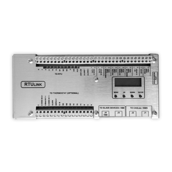
Page 6: Overview
“THERMOSTAT” side of the board and will be referred as such throughout the document. In Figure 1, the right side of the RTULink is the “RTU” side of the board and will be referred to as such throughout the document. -
Page 7: Installation Of Hardware Components
RTULink Open the controls cabinet of the RTU that is being equipped with an RTULink. Locate a spot in the controls cabinet that will accommodate the footprint of the RTULink, leaving a few inches on each side for wiring. Do not alter RTU factory wiring configuration. - Page 8 Label the wires for the outside air thermistor and wire it to the positive (+) and common (C) terminals (thermistor input is not polarity sensitive) labeled “OUTSIDE AIR TEMP SENSOR 10kΩ” on the TO RTU side of the RTULink control board.
-
Page 9: Rtulink To Rtu Wiring
RTULink to RTU Wiring The RTULink will Table 1. RTULink to RTU Wiring Terminals need to be wired to the RTU in order to TERMINAL SIGNAL RTULINK SIGNAL DESCRIPTION send control signals. LABEL VOLTAGE INPUT/OUTPUT Table 1 details the 24VAC THERMOSTAT TRANSFORMER “RTU”... -
Page 10: Thermostat (Optional)
Thermostat (optional) If a traditional external thermostat will be used to control the RTU, follow these instructions. The thermostat that is being Table 2. Thermostat to RTULink Wiring Terminals used to control the RTU will TERMINAL SIGNAL RTULINK need to be wired to the... -
Page 11: Space Thermistor - Wall Mount (Optional)
Figure 7. Thermostat - RTULink Installation Detail Space Thermistor – Wall Mount (optional) If a space temperature sensor/thermistor is called for in the specifications, follow the instructions in this section. Note: This is not to be confused with the traditional space stat that is used for commercial kitchen ventilation electrical packages. - Page 12 Figure 9. Space Thermistor Detail (Plastic Housing Wall Mount) Figure 10. Space Temperature – RTULink Wiring...
-
Page 13: Modbus Communication Wiring
See APPENDIX A for typical network layouts in order to determine the best configuration for the application. Use the J1 and J2 RJ45 ports to connect the RTULinks together using the CAT5 cable. If an RTULink is the last in a line, it will only have one CAT5 cable connected to it and will require an end of line resistor (PN: EOL120A) in its unused port (J1 or J2). -
Page 14: Optional Sensors
“RTU” Input 1 on the Figure 12. Temperature and Humidity Sensor Detail (Plastic Wall Mount) RTULink. Standard 18-5 thermostat wire should be used for sensor wiring. Figure 13. Temperature and Humidity Sensor Detail (Stainless Steel Wall Mount Housing) - Page 15 Figure 14. Once the sensor is wired to an input, enter the configuration menu of the RTULink via the onboard HMI and configure the corresponding input for the humidity sensor that was installed. In the Figure 14 example, “RTU IN 1” would be configured for “SPACE RH”.
- Page 16 HMI and configure the corresponding input for the Outdoor Air humidity sensor that was installed. In the above example, “RTU IN 1” would be configured for “OA RH”. Figure 16. RTULink - Outside Air Temp and RH...
-
Page 17: Relative Humidity - Duct Mount (Return Or Discharge)
Figure Figure 18 is a wiring diagram of a duct mounted humidity sensor that is wired to the “RTU” Input 1 on the RTULink. Once the sensor is wired to an input, enter the configuration menu via the... -
Page 18: Carbon Dioxide Sensor - Duct Mount
RTULink. The output voltage of the CO sensor will need to be wired to a 0-10VDC input on the sensor wired to Input 1 on the “RTU” side of the RTULink can be seen in Figure 20. RTULink. A wiring diagram of a CO Standard 18-5 wire should be used for sensor wiring. -
Page 19: Current Transducer
80 amp). Connect the positive (+) and negative (-) terminals of the current transducer to the positive (+) and negative (-) terminals of a 0-10VDC input on the RTULink. PN: A/CTV-50 is used to measure components in the range of 10, 20, and 50 amps. -
Page 20: Optional Outputs
Optional Outputs Damper/Economizer (0-10VDC) If the RTULink will be controlling an 0-10VDC damper or economizer, it must be configured to accommodate this feature. Choose a 0-10VDC output on the “RTU” side of the RTULink that will be controlling the economizer. Figure 23 is a... -
Page 21: Powered Exhaust Coil Signal On/Off (24Vac)
Note: This is a low voltage, low amperage control signal that does not provide power to the powered exhaust but signals a variable speed Figure 25. RTULink - Powered Exhaust Connected to Output #2 (0-10VDC) -
Page 22: Occupied/Unoccupied Signal (24Vac)
Once this feature is enabled, the RTULink must we wired accordingly. Wire the DEFROST terminal on the TO THERMOSTAT side of the RTULink to the RTU occupied terminal (this will send the occupied signal to the RTU). If an external thermostat is going to be wired... -
Page 23: Start-Up Procedure
This startup procedure should be followed once the installation procedure has been completed for all RTULinks at the site. The HMI on the RTULink has four buttons below the screen that are labeled “MENU”, “UP”, “DOWN”, and “ENTER”. Pressing “MENU” backs out one menu selection and is the opposite of pressing “ENTER”. Pressing “UP” or “DOWN”... -
Page 24: Rtulink Modes Of Operation
RTULinks at a site be configured for the same operational mode. Global scheduling abilities via CASLink will be lost if RTULinks are set to different operational modes. Once a mode is configured on the RTULink, the configuration menu will hide parameters that do not pertain to the current control mode. To get a full list of the settings that apply to a control mode, view the FUNCTIONALITY section of this manual. -
Page 25: Functionality
HP O/B Mode - Heat pump O/B mode sets whether the O/B terminal is energized with a call for heating or a call for cooling. If “energize w/ heat” is selected, the RTULink will signal a call for heating with terminals Y and O/B. - Page 26 HMI ‘x’ Avg Enable - Sets if averaging is ON or OFF. Heating SP - The heating set point is the default set point that the RTULink defaults to if it ever comes out of a schedule from CASLink or has never received a schedule from CASLink (during startup). If the tempering sensor is below this set point plus the Heat Hysteresis value, the RTULink will send a signal for heating.
- Page 27 Max X Stg RunTim - Maximum X stage runtime is the maximum time that a stage is allowed to run before the RTULink calls for the next stage (if applicable). For example, if stage x has been running for the duration of this timer, then force stage x+1, if the unit is equipped with a stage x+1.
- Page 28 Out #1 Range - Output 1 range is the voltage range that the component connected to output 1 is designed to operate with. Once set, the RTULink will use the low-end voltage of this range for an OFF signal and the high- end voltage of this range for a fully modulated ON signal.
-
Page 29: Faults
Scheduling - Menu to set scheduling to be ON or OFF. If disabled, the RTULink will always operate with the default settings configured through the board HMI. If enabled, settings can be overridden through CASLink. Occ Override - Menu to set occupied override to be ON or OFF. When set to ON, the state of occupancy can be overridden on the HMI. -
Page 30: Main Board Hmi Menu Tree
Main Board HMI Menu Tree... -
Page 35: Space Hmi And Remote Room Sensor Installation
Space HMI and Remote Room Sensor Installation Space HMI faceplate(s) (refer to Figure 28), remote room sensors (refer to page 11 and page 14 for optional sensors), and smart controls may be ordered and shipped separately. These components measure temperature and assist in controlling the unit. -
Page 36: Space Hmi Operation
Remote (HMI) Control Panel On units shipped with a space HMI, a Cat 5 cable will need to be run from RTULink board J4 to J2 on the HMI. If additional space HMIs have been added, they can be daisy-chained from the first HMI. An end of line resistor should be added to the last HMI in the chain. -
Page 37: Factory Settings
Stage Runtimes Max Runtime – Maximum time that a stage is required to run before the RTULink will allow a call for the next stage (if applicable). For example, if stage x has been running for the duration of this timer, then force stage x+1, if the unit is equipped with a stage x+1. - Page 38 Occ Intlk – When set to Passthru, allows a hardware input (on the ALARM terminal of the stat side of the RTULink) which will output a defrost signal to the RTU side. When set to Interlock, this will force the RTULink into an occupied state in scheduling and forces the blower on.
- Page 39 Outdoor Air Config 0-10V Damper – When set to OFF, no output to the damper from the RTULink board. When set to ON, an output signal is sent from the RTULink board to the damper. Min OA Damper – The minimum percentage the outdoor damper will operate.
-
Page 40: Service
0-10VDC signal. VDC Out1 – Output #1 configures the use for OUT #1 on the “To RTU” side of the RTULink. VDC Out2 – Output #2 configures the use for OUT #2 on the “To RTU” side of the RTULink. -
Page 45: Troubleshooting
STAT Alarm view the RTU manufacturers manual to determine the meaning of the of the RTULink is signal that is connected to Alarm 1 on the “RTU” side of the RTULink active. Temperature sensor Verify correct resistance across Type II 10kΩ thermistor and replace if... - Page 46 Enthalpy economizer Verify that an outside air relative humidity sensor is connected to one of is configured on the the RTULink inputs. Install and connect one if one has not already Outside RH Not RTULink but an been connected. Once the sensor is connected, configure the sensor...
-
Page 47: Component Description
COMPONENT DESCRIPTION Temperature Sensor – Wall Mount A wall mount thermistor may be used to monitor a space temperature. The thermistor is a Type II 10kΩ thermistor that provides a constant space temperature reading to the control board. It should be installed on a junction box, which should be mounted in a space that gives an accurate reading. -
Page 48: Temperature And Humidity Sensor - Outdoor Mount
Temperature and Humidity Sensor – Outdoor Mount One or several outdoor air temperature and humidity sensors may be utilized at a site. The sensor contains a Type II 10kΩ thermistor for the temperature reading and a 0-10VDC relative humidity sensor for the humidity reading. This sensor can be mounted using ½” EMT conduit or by securing the sensor housing with approved fasteners. -
Page 49: Daisy Chain Topology
APPENDIX A NOTE: DO NOT ROUTE COMMUNICATION WIRING WITH HIGH VOLTAGE WIRES Daisy Chain Topology: Figure 29. Daisy Chain – Ideal Configuration Star Topology: Figure 30. Star... - Page 50 APPENDIX B 1. Strip the CAT5 cable and arrange the wires in the color configuration seen below. Figure 31. Straight-Through Wiring Configuration Figure 32. RJ45 Pinout...
- Page 51 Figure 33. Looking Into Rear Opening of RJ45 Connector Match the numbers of the wire color coding in Figure 31 with the numbers in Figure 33. NOTE: Figure 33 is the view looking into the rear opening of the RJ45 connector. Ensure that the wires are completely inserted into the connector.
-
Page 52: Fixed Dry Bulb Economizer
APPENDIX C Fixed Dry Bulb Economizer Figure 34. Fixed Dry Bulb Economizer Operation... -
Page 53: Differential Dry Bulb Economizer
Differential Dry Bulb Economizer Figure 35. Differential Dry Bulb Economizer Operation... -
Page 54: Fixed Enthalpy Economizer
Fixed Enthalpy Economizer Figure 36. Fixed Enthalpy Economizer Operation... -
Page 55: Differential Enthalpy Economizer
Differential Enthalpy Economizer Figure 37. Differential Enthalpy Economizer Operation... -
Page 56: Start-Up And Maintenance Documentation
Start-Up and Maintenance Documentation Job Information Job Name Service Company Address Address City City State State Phone Number Phone Number Fax Number Fax Number Contact Contact Purchase Date Startup Date MAC Address: Static IP if Assigned: Maintenance Date Service Performed Factory Service and Support Department Phone: 1-866-784-6900 Fax: 1-919-554-9374...
Need help?
Do you have a question about the RTULink and is the answer not in the manual?
Questions and answers